Table 4. dip switches, Table 4 – ADTRAN FXS/DPO/PLAR 1109403L2 User Manual
Page 5
61180403L1-5B
Issue 2, December 2004
5
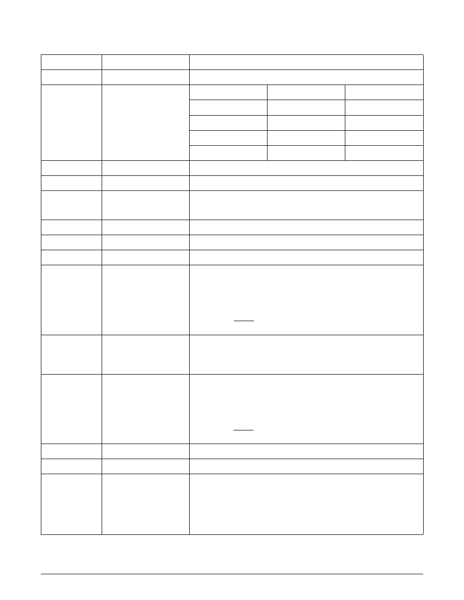
Table 4. DIP Switches
Sw.-Segment
Label
Function/Description
1-1
D3/D4
D3 or D4 Signaling (PLAR only)
1-2
1-3
MODE 1/OFF
MODE 2/OFF
SW1-2
SW1-3
Mode Selected
OFF
OFF
FXS
OFF
MODE 2
DPO
MODE 1
OFF
Tandem
MODE 1
MODE 2
PLAR
1-4
GS/LS
Ground Start or Loop Start
1-5
AUTO_TERM/OFF
Reserved for future use
1-6
900/600
Selects the Impedance of the 2-wire interface:
900 + 2.16 µF or 600 + 2.16 µF
1-7
RTG/OFF
Ringback Tone Generation (tandem and PLAR modes only)
1-8
DTG/OFF
Dialtone Generation (tandem and PLAR modes only)
2-1
DPC/OFF
Reserved for future use
2-2
2-3
2-4
2-5
2-6
2-7
2-8
RX64/OFF
RX32/OFF
RX16/OFF
RX08/OFF
RX04/OFF
RX02/OFF
RX01/OFF
Receive attenuation in 0.1 dB increments (values are additive up to a total
of 9.0 dB)
Example:
RX32 = 3.2 dB
RX01 = 0.1 dB
3.3 dB Total receive attenuation
3-1
SD/OFF
Selects signaling on the loop during a Carrier Fail Alarm (CFA)
SD = Busy during CFA
OFF = Idle during CFA
3-2
3-3
3-4
3-5
3-6
3-7
3-8
TX64/OFF
TX32/OFF
TX16/OFF
TX08/OFF
TX04/OFF
TX02/OFF
TX01/OFF
Transmit attenuation in 0.1 dB increments (values are additive up to a
total of 7.0 dB)
Example:
TX32 = 3.2 dB
TX01 = 0.1 dB
3.3 dB Total transmit attenuation
4-1
IMM/WINK
Tandem start mode: Immediate or Wink Start
4-2
REV/NORM
Tandem battery mode: Reverse or Normal battery
4-3
4-4
4-5
4-6
4-7
4-8
NB64/OFF
NB32/OFF
NB16/OFF
NB08/OFF
NB04/OFF
NB02/OFF
Network Build Out Capacitance (NBOC) in 2 µF increments (values are
additive)