American Fibertek Commander C10e/C10e-I/C10p/C10p-I User Manual
Page 48
48
Port Numbers: Commander’s port numbers are expressed two ways. The physical ports
are identified as Ports 00 through 10. The logical numbering system is Ports 1-11.
Logical Port 11 is Commander’s internal CPU port. This port carries signals from the
Ethernet switch to the internal processor. If communication is lost from this port, the
switch will lose some functions that require the CPU, such as STP, RSTP and
Multicasting. The CPU port is always connected to the same VLAN as logical Port 1.
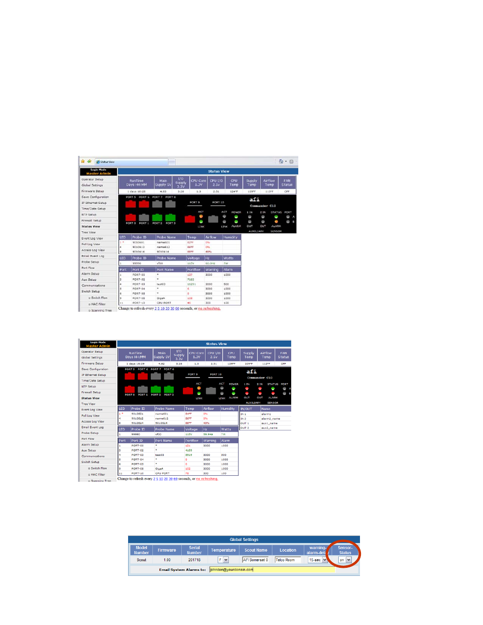
Status View: Ports
The Status View is divided into 4 sections.
Internal Conditions
Environmental: Temperature/Airflow/Humidity
Power: Voltage/Frequency/Power
Port Conditions: PortFlow™
Status View: Alarms and Auxiliaries
When hard contract alarms or
auxiliaries are active, they will
be displayed in the Status View
Commander can monitor communications with its probes if the Sensor Status is set to on in the
Global Settings. When set to on the LED will display a solid amber color during the
communication process. Please note in the default setting all probes will only address LED # 1
until the programming has been changed. Global settings are a Master Admin function only.