American Fibertek Commander C10e/C10e-I/C10p/C10p-I User Manual
Page 13
13
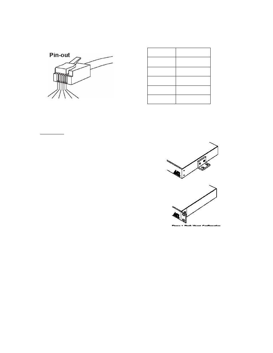
1
Common
2
IN -
3
IN +
4
OUT +
5
OUT -
6
Common
RS485 Connector
1 - 6
The RS232 connections is a standard DB9 DTE configuration
Installation
To install the Commander it is first necessary to mount
the rack flanges to the unit. Two mounting flanges are
supplied with each Commander. For flush mounting,
install the ears with the #10 flathead screws provided
There are two rack mounting options.
A
single
Commander can be installed in a rack using the half
rack mounting kit C10-HRM. Two Commanders may
be rack mounted side by side with a C10-FRM kit.
For rack mounting the ears are installed on the sides of
the unit with the surfaces that have oval holes flush
with the front of the unit as in Figure 1. Mount the ears
with the #10 flathead screws provided. To mount in
the rack cabinet, use mounting screws that are
appropriate for the rack cabinet being used.
Power Source
The internal power supply accepts universal line voltage. Any mains supply from (85 to 264
VAC), (47 to 63 Hz) may be used without modification or adjustment. A universal power
connector is provided on the rear of the unit to facilitate connection to the power mains.
Power Connection
The unit is supplied (in the US and UK only) with a three conductor power cord. The “ground”
conductor is directly connected to the chassis.