American Fibertek Commander C10e/C10e-I/C10p/C10p-I User Manual
Page 10
10
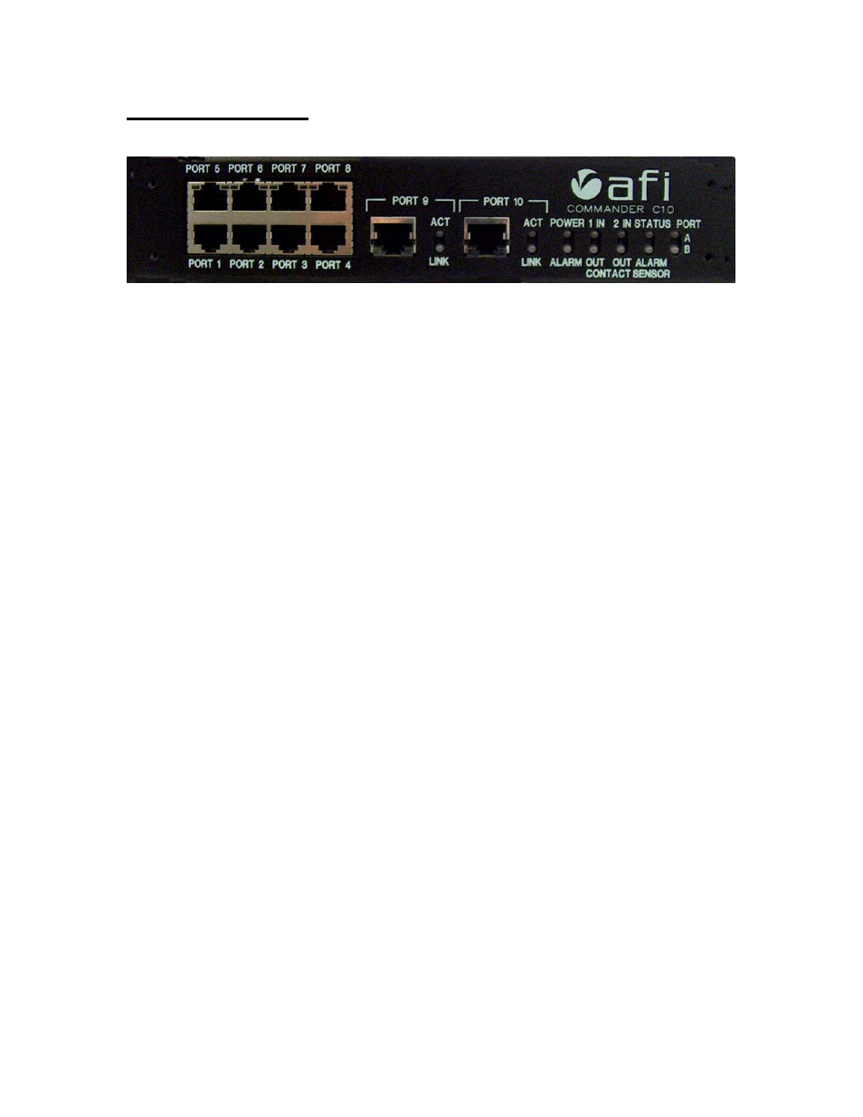
Commander Front Panel
Power: There are two power indicators, one for power supply and one for power status.
The Power LED illuminates green when power is applied.
The Alarm LED is green for normal operation and will turn red for alarm conditions on any of the
internal temperature monitors or power supply voltage monitors.
Solid Green = Normal Operation
Solid Red = Alarm Condition Present
Flashing Green= Unit booting up
Ports 1 through 8:
Port 9 & 10:
10/100baseTx Ethernet Ports:
1000baseT Ethernet Ports:
Link – Off – No connection
Link – Off – No connection
Amber - 10 Mb/s
Amber - 10 or 100 Mb/s
Green - 100 Mb/s
Green - 1000 Mb/s
Act -
Off – No data activity
Act -
Off – No data activity
Amber Flashing – Data activity
Amber Flashing – Data activity
Alarm In: The default alarm condition is a closed contact. If the NC check box is active for an
alarm input, then the alarm condition will be an open contact. Alarm contact LED’s are per
“current status”.
Normal condition - Off
Alarm condition - Red
Auxiliary out: Auxiliary contact LED’s are per “current status”.
Normal condition - LED is off
Relay Activated - LED will be red