2 the rear panel – Nilfisk-ALTO 3.4 User Manual
Page 6
5
8.ENTER key
The key allows you to access to the selected editing
. P
ou can edit and confirm
value of parameter.
page
ressing this key, y
the required
10.Input Level LEDs
The LEDs are used to indicate the level of input A/B. In order to get an up-front distortion-free signal, you keep
the signal quite high, but do assure that the red CLIP LED doesn't light up continually.
11.Mute switches
There are six mute switches (1-6). They are used to mute the signal of the respective outputs. When the switch
is on, the corresponding led will light up. These switches can avoid signal peaks when switching on and off the
sound system and isolate the individual audio sections during testing or checking sound, etc.. The restored Mute
function can be set to use the Wake Up Function (Utility menu Misc. Setup submenu) and can be set as Normal
(last setting before the unit was switched off) or Mute (all outputs automatically forced into Mute status).
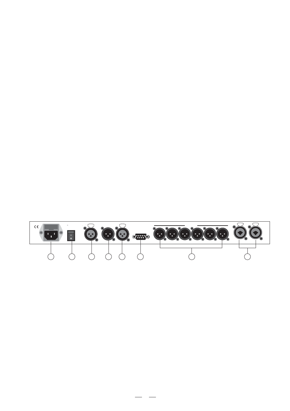
3.2 The Rear Panel
7.Memory Card Slot
The Slot allows you to insert the Memory Card which is very useful for safe storage of PRESETS and for
one MAXIDRIVE3.4 to another.
their
transfer from
19
13
20
14
15
16
17
18
PUSH
2
1
3
NEW
TIDE
PUSH
2
1
3
NEW
TIDE
Apparaten skall anslutas till
jordat uttag nar den ansluts
till ett natverk
PWR
OFF
ON
AC INPUT
14W
95-240V
50/60Hz
FUSE: 95-120V T500mAL
210-240V T315mAL
DIGITAL IN
RS485 OUT
RS485 IN
RS232
INPUT A
INPUT B
4
3
2
1
OUTPUTS
5
6
A102
9.ESC key
The key allows you to exit the selected editing page. It also used to reject the value to enter and return to the
stored value.
12.Output Level LEDs
These LEDs indicate the level of the respective outputs (you can adjust the output via adjusting the Output Gain
parameter of Edit menu.)
Note: The LIMITER on any output will change the way in which the level is displayed on the corresponding LED.
In fact, the level shown on the ladder is no longer the "absolute" output level, but the level of the signal at -24dB,
-12dB, -6dB compared to the limiter threshold (indicated by the orange LIMIT LED).
PUSH
1
3
2
NEW
TIDE
PUSH
1
3
2
NEW
TIDE
13.AC inlet and fuse holder
CAUTION: If there is something wrong with the fuse or the fuse needs to change, please refer to a qualified
technician. If the fuse continues to blow after replacing, discontinue using of this unit before being repaired.
14.Power Switch
The switch is used to turn the main POWER on and off. Note: before turning on the unit, please make sure the
amplifiers of the sound system are off to avoid the annoying and sometimes dangerous signal peaks.
15.Digital In
Use the balanced XLR-F connector (one cable is enough to feed both inputs connect the processor to units fitted
with AES/EBU digital outputs. In this case, the two bypassed convention will improve the quality of the signal.
A signal connected to the digital input has the same processing as that connected to analog input. The Digital/
Analog input selection can be set by using the Input Select function (Utility Menu-Misc. Setup Submenu).
Use it to connect your MAXIDRIVE3.4 to the supplied AC cord. Please check the Voltage in your country and
what voltage for your MAXIDRIVE3.4 is configured before attempting to connect the unit for the main AC. The
fuse can protect the AC supplies circuit of the equipment.