Digital inputs analog inputs – Nilfisk-ALTO 3.4 User Manual
Page 27
26
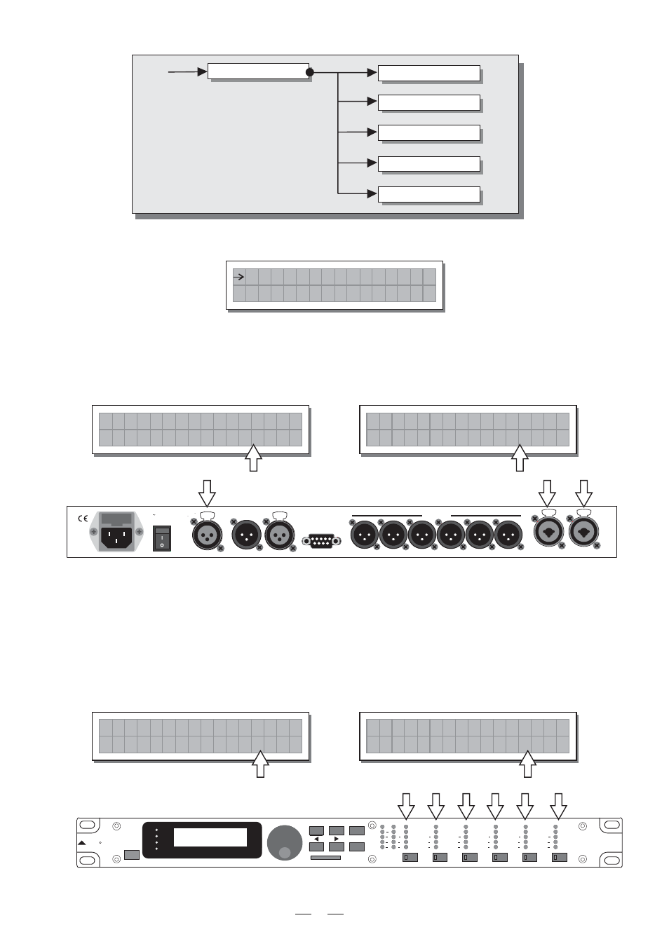
5.4.3 Misc. Setup submenu
Use this submenu to set a series of system options.
a. Input Select
Used to choose
which MAXIDRIVE3.4 should use.
inputs
The options include:
The inputs selected become
and
.
Any signal on the inputs not selected is ignored.
Input A
Input B
b. Output Meters
Used to decide whether to display the outputs signal before or after MUTE.
The options include:
Input Select
Output Meters
Misc. Setup
Temperature
Wake Up
LCD Contrast
M i s c .
S e t u p
I n p u t
S e l e c t
A n a l o g
PreMute
the signal is always shown
no matter what the MUTE status
u t p u t
M e t e r s
P r e M
t e
O
u
PostMute
the signal is only shown if
the output isn't in MUTE
u t p u t
M e t e r s
o s t M
t e
O
u
P
PUSH
2
1
3
NEW
TIDE
PUSH
2
1
3
NEW
TIDE
Apparaten skall anslutas till
jordat uttag nar den ansluts
till ett natverk
PWR
OFF
ON
AC INPUT
14W
95-240V
50/60Hz
FUSE: 95-120V T500mAL
210-240V T315mAL
DIGITAL IN
RS485 OUT
RS485 IN
RS232
INPUT A
INPUT B
4
3
2
1
OUTPUTS
5
6
A102
3-WAY STEREO
DIGITAL CROSSOVER
MAXIDRIVE3.4
ENTER
R
LTO
PREV
NEXT
ESC
MODE
CLIP
6
12
18
24
A
B
INPUT LEVEL
MUTE
CLIP
6
12
24
LIMIT
OUTPUT
2
LEVEL
CLIP
6
12
24
LIMIT
CLIP
6
12
24
LIMIT
CLIP
6
12
24
LIMIT
CLIP
6
12
24
LIMIT
CLIP
6
12
24
LIMIT
OUTPUT
1
LEVEL
OUTPUT
3
LEVEL
OUTPUT
4
LEVEL
OUTPUT
5
LEVEL
OUTPUT
6
LEVEL
MUTE
MUTE
MUTE
MUTE
MUTE
EDIT
UTILITY
DELAY
PRESET
CARD
I n p u t
S e l e c t
i g i t a l
D
PUSH
1
3
2
NEW
TIDE
PUSH
1
3
2
NEW
TIDE
Digital Inputs
Analog Inputs