HP 1.10GB Virtual Connect Ethernet Module for c-Class BladeSystem User Manual
Page 70
Network management 70
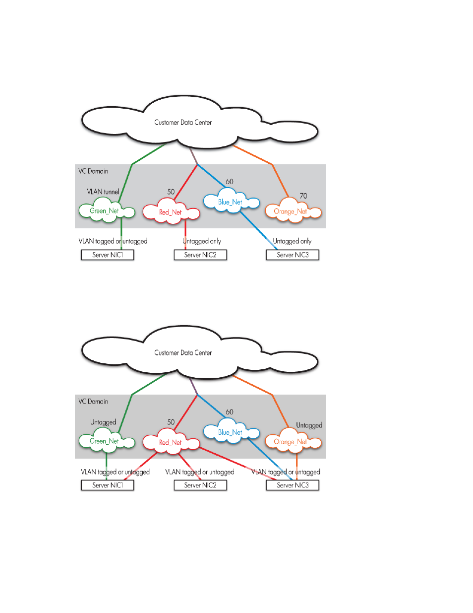
The following figure shows tunneled VLAN tags. On the dedicated, green network, both uplink and server
VLAN tags are tunneled through Virtual Connect unchanged. On the shared, red and blue networks,
uplink VLAN tags are mapped to networks. Untagged frames are mapped to the native VLAN, if present,
otherwise they are dropped. Server frames are untagged only, and tagged frames are dropped. Each
server port is connected to a single network.
The following figure shows mapped VLAN tags, a feature that enables users to define how each server
VLAN tag is mapped to a specific network. Each server port can connect to multiple networks. Server
NIC1 is connected to both the Green and Red networks. Server NIC2 is connected to the Red network,
and Server NIC3 is connected to the Red, Blue, and Orange networks. All server NICs can send and
received tagged or untagged traffic.
If Virtual Connect is set to map VLAN tags, VC-Enet modules accept incoming frames with valid server
VLAN tags and translate server-assigned VLANs into corresponding internal network VLANs, thus placing
the server packet on the correct network. When these frames reach the uplinks, network VLANs are once
again translated into external data center VLANs. Similarly, VLANs are translated back to server-assigned
VLANs (or stripped and untagged) before sending frames out to servers. This function allows for the
- Virtual Connect 4Gb Fibre Channel Module for c-Class BladeSystem Virtual Connect 8Gb 20-port Fibre Channel Module for c-Class BladeSystem Virtual Connect Flex-10 10Gb Ethernet Module for c-Class BladeSystem Virtual Connect 1.10Gb-F Ethernet Module for c-Class BladeSystem 4GB Virtual Connect Fibre Channel Module for c-Class BladeSystem Virtual Connect 8Gb 24-port Fibre Channel Module for c-Class BladeSystem