Asus M2R-FVM User Manual
Page 39
ASUS M2R-FVM
1-27
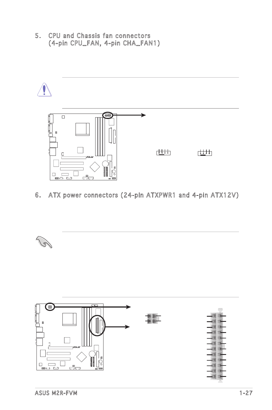
5. CPU and Chassis fan connectors
(4-pin CPU_FAN, 4-pin CHA_FAN1)
The fan connectors support cooling fans of 350mA~740mA (8.88W
max.) or a total of 1A~2.22A (26.64W max.) at +12V. Connect the fan
cables to the fan connectors on the motherboard, making sure that the
black wire of each cable matches the ground pin of the connector.
Do not forget to connect the fan cables to the fan connectors.
Insufficient air flow inside the system may damage the motherboard
components. These are not jumpers! DO NOT place jumper caps on the
fan connectors.
R
M2R-FVM
M2R-FVM Fan Connectors
CPU_FAN
GND
CPU F
AN PWR
CPU F
AN IN
CPU F
AN PWM
CHA_FAN1
GND
CHA F
AN PWR
CHA F
AN IN
CHA F
AN PWM
6. ATX power connectors (24-pin ATXPWR1 and 4-pin ATX12V)
These connectors are for ATX power supply plugs. The power supply
plugs are designed to fit these connectors in only one orientation.
Find the proper orientation and push down firmly until the connectors
completely fit.
• Do not forget to connect the 4-pin ATX +12 V power plug;
otherwise, the system will not boot.
• Use of a PSU with a higher power output is recommended when
configuring a system with more power-consuming devices. The
system may become unstable or may not boot up if the power is
inadequate.
• Make sure that your power supply unit (PSU) can provide at least
the minimum power required by your system.
R
M2R-FVM
M2R-FVM ATX Power Connector
ATXPWR1
ATX12V1
+3 Volts
+3 Volts
Ground
+5 Volts
+5 Volts
Ground
Ground
Power OK
+5V Standby
+12 Volts
-5 Volts
+5 Volts
+3 Volts
-12 Volts
Ground
Ground
Ground
PSON#
Ground
+5 Volts
+12 Volts
+3 Volts
+5 Volts
Ground
GND
GND
+12V DC
+12V DC