Fire and explosion hazard, Breathing hazard - carbon monoxide gas – American Water Heater HCG3 130T 300 User Manual
Page 51
51
to a common gas main firing at full capacity.
note: A pressure drop of more than 1.5” W. C. (0.37 kPa) when
the Main Burner ignites is an indication of an inadequate supply
of gas and can lead to ignition failure, rough starts and/or rough
operation. If a drop of more than 1.5” W. C. (0.37 kPa) in supply
gas pressure occurs when the Main Burner ignites, ensure
the supply gas lines and regulator(s) are properly sized and
installed. See the requirements for Supply Gas Regulator and
Supply Gas Line on page 13. See Supply Gas Line Installation on
page 37 and Supply Gas Regulator Installation on page 38. Ensure
all requirements and installation instructions are maintained.
manifold gas pressure adjustment
Fire and Explosion Hazard
Gas and carbon monoxide detectors are
available.
Overfiring could result in fire or
explosion.
Under no circumstances should the
input exceed the rate shown on the
water heater’s rating label.
Breathing Hazard - Carbon Monoxide Gas
Breathing carbon monoxide can cause brain damage or
death. Always read and understand instruction manual.
Under no circumstances should
the input exceed the rate shown
on the water heater’s rating label.
Overfiring could result in damage to
the water heater and sooting.
Gas and carbon monoxide detectors
are available.
Ensure the "dynamic" supply gas pressure is above the minimum
requirements in Table 4 on page 13 before any adjustments are
made to the manifold gas pressure. Attempts to adjust manifold
gas pressure during periods of low supply gas pressure could
result in overfiring when the supply gas pressure returns to
normal. See Supply Gas Pressure Adjustment on this page.
If necessary, adjust the manifold gas pressure as follows:
1. Follow the instructions for Initial Start Up on page 50 to connect
manometers to the supply and manifold gas pressure taps
and to start the water heater.
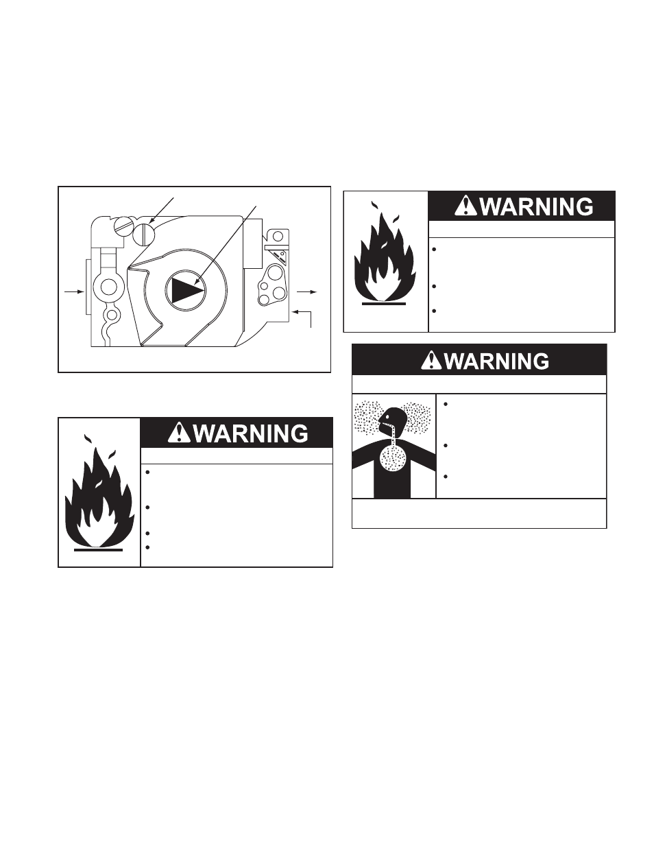
2. Remove the manifold gas pressure regulator cover screw,
see Figure 56.
3. Using a small flat tip screw driver turn the adjustment screw
clockwise to increase manifold gas pressure and counter
clockwise to decrease manifold gas pressure.
note: Turn the manifold gas pressure adjustment screw
in small increments (no more than 1/4 turn) and allow the
manifold gas pressure to stabilize for several minutes before
making further adjustments.
4. Replace the gas pressure regulator cover screw.
5. Cycle the burner on and off several times to check operation.
6. Compare the actual manifold gas pressure reading recorded
above to the required minimum/maximum values given in
Table 4 on page 13. Adjust manifold gas pressure as necessary,
see the instructions that follow.
7. Record the supply gas pressure when the 24 VAC Gas
Valve is energized and the Main Burner is ignited. This is a
“dynamic” gas pressure reading; while the water heater is
firing.
8. Compare the actual supply gas pressure reading recorded
above to the required minimum/maximum values given in
Table 4 on page 13. Adjust supply gas pressure as necessary,
see the instructions that follow.
ON
OFF
HONEYWELL
MANIFOLD GAS
PRESSURE REGULATOR
COVER SCREW
24 VAC GAS VALVE TOP VIEW
MANIFOLD GAS
PRESSURE TAP
1/8’ NPT PLUG
INLET
OUTLET
GAS CONTROL
KNOB
figure 56
supply gas pressure adjustment
Fire and Explosion Hazard
Turn off gas lines during installation.
Contact a qualified installer or service
agency for installation and service.
Excessive gas pressure to gas valve can
cause serious injury or death.
Do not use water heater with any gas
other than the gas shown on the rating
label.
Supply gas pressure shall be measured while the water heater is
not firing (static pressure) AND while the water heater is firing at
full capacity (dynamic pressure).
If the supply gas pressure to the water heater is not between the
required minimum and maximum values given in Table 4 on page
13 adjust the supply gas regulator as necessary. Adjust the supply
gas regulator(s) per the regulator manufacturer’s instructions to
achieve the required “static” and “dynamic” supply gas pressure.
multiple appliance installations:
In multiple water heater installations or in installations where
the installed water heater(s) share a common gas supply main
with other gas fired appliances; the supply gas pressures shall
be measured at each water heater with all gas fired appliances
connected to a common main firing at full capacity.
On multiple water heater installations the supply gas line regulators
shall be adjusted to provide gas pressure to each water heater
within the minimum and maximum supply pressure requirements
listed in Table 4 on page 13 with all gas fired appliances connected