Ampro Corporation DLP 5200 User Manual
Page 46
Connector Pin Assignments
44
5200 User’s Manual
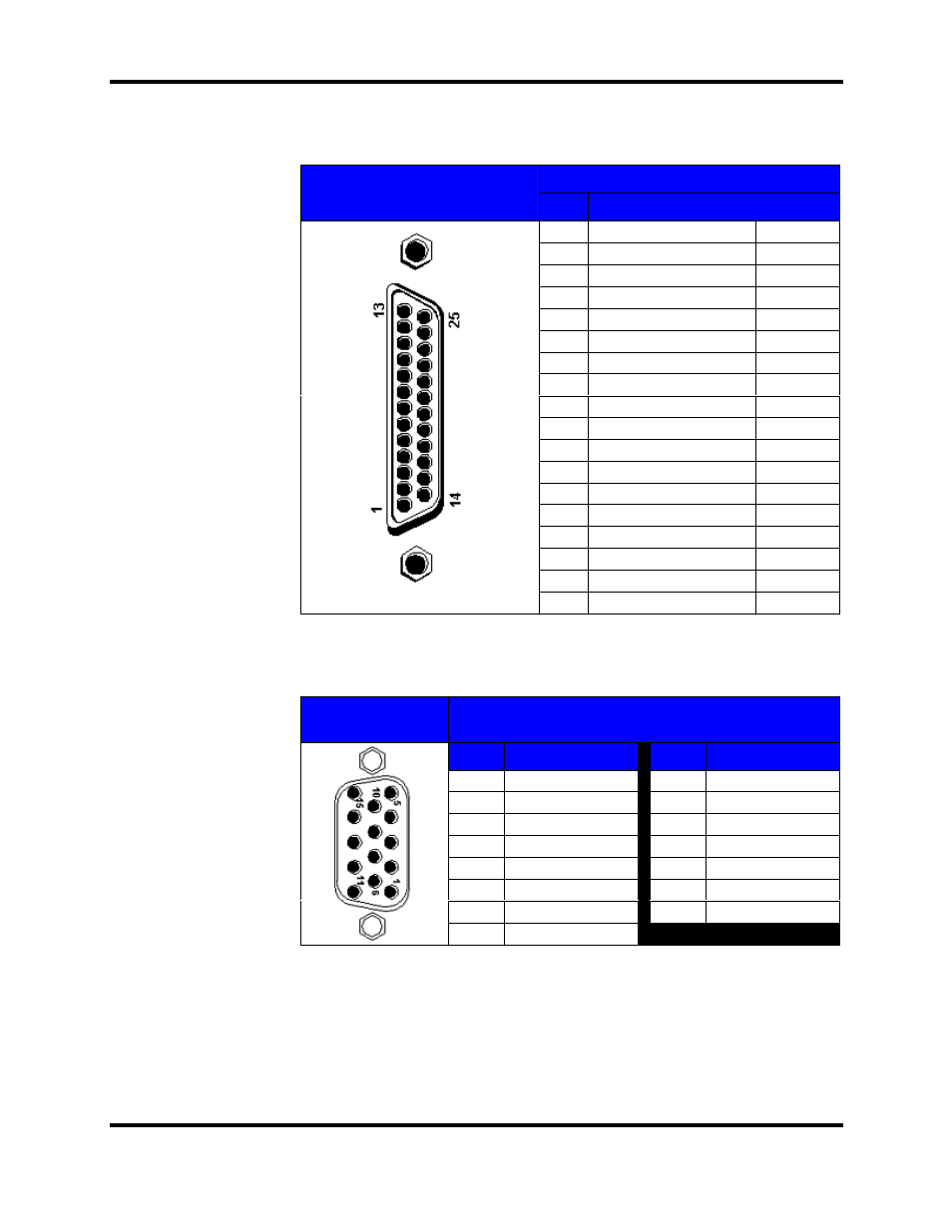
LPT2 Pin Assignments
LPT2 Pin Numbers
PIN
SIGNAL
1
Strobe
STB#
2
Printer Data Bit 0
PD0
3
Printer Data Bit 1
PD1
4
Printer Data Bit 2
PD2
5
Printer Data Bit 3
PD3
6
Printer Data Bit 4
PD4
7
Printer Data Bit 5
PD5
8
Printer Data Bit 6
PD6
9
Printer Data Bit 7
PD7
10
Acknowledge
ACK#
11
Busy
BUSY
12
Paper End
PE
13
Select
SLCT
14
Automatic Feed
AFD#
15
Error
ERR#
16
Initialize Printer
INIT#
17
Select In
SLIN#
Parallel Port (LPT2)
If you reconfigure your
hardware, you may need
the pin numbers and
assignments for the
parallel port connector.
The figure below
illustrates the pin
numbers for the parallel
port connector and the
Table (to the right) list
and defines the pin
assignments for the
parallel port connector.
18-25 Signal Ground
GND
RGB2 Pin
Numbers
RGB2 Pin Assignments
PIN
SIGNAL
PIN
SIGNAL
1
Red Video
9
No Pin
2
Green Video
10
Ground
3
Blue Video
11
ID Bit
4
ID Bit
12
ID Bit
5
Self Test
13
Horizontal Sync
6
Red Return
14
Vertical Sync
7
Green Return
15
ID Bit
RGB2 Input
(HD15 pin)
8
Blue Return