Figure 8 chilled water coil pressure drop chart – Sterlco SBFC Series Blown Film Coolers User Manual
Page 19
SBFC Series Blown Film Cooling Systems
Page 19
Figure 7
Air Flow, Required Cooling, and Piping Specifications
Air flow
Nominal cooling
Water
3-way regulating
Condensation
Model
rated hp / kW
required
c
capacity
Pipe size
valve size
drain size
no.
cfm
cmh
tons
Kcal/hr
gpm
lpm in. NPT approx. mm in. NPT approx. mm in. NPT approx. mm
SBFC-600
600 1,019
7.3
22,075
21
79.5
1”
25.4 mm
¾”
19.0 mm
¾”
19.0 mm
SBFC-1000 1,000 1,699 12.1
36,590
34
128.7
1¼”
31.7 mm
1”
25.4 mm
¾”
19.0 mm
SBFC-1500 1,500 2,548 18.2
55,037
52
196.8
1½”
38.1 mm
1¼”
31.7 mm
¾”
19.0 mm
SBFC-2000 2,000 3,398 24.2
73,181
69
261.2
2”
50.8 mm
1½”
38.1 mm
¾”
19.0 mm
SBFC-3500 3,500 5,946 42.4
128,217
100
378.5
2½”
63.5 mm
2”
50.8 mm
¾”
19.0 mm
SBFC-5000 5,000 8,495 60.5
182,952
145
548.8
2½”
63.5 mm
2”
50.8 mm
¾”
19.0 mm
c Entering air @ 100ºF (38ºC) dry bulb, 80ºF (27ºC) wet bulb, 40ºF (4ºC) chilled water = 50ºF (10ºC) leaving air temperature.
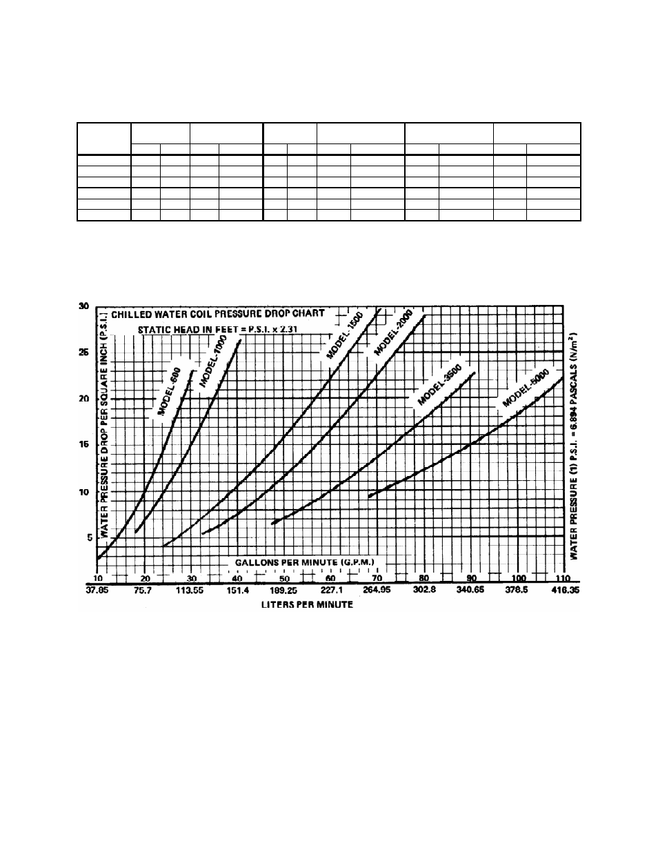
Figure 8
Chilled Water Coil Pressure Drop Chart