Figure 3 sbfc standard dimensions cont’d – Sterlco SBFC Series Blown Film Coolers User Manual
Page 11
SBFC Series Blown Film Cooling Systems
Page 11
Figure 3
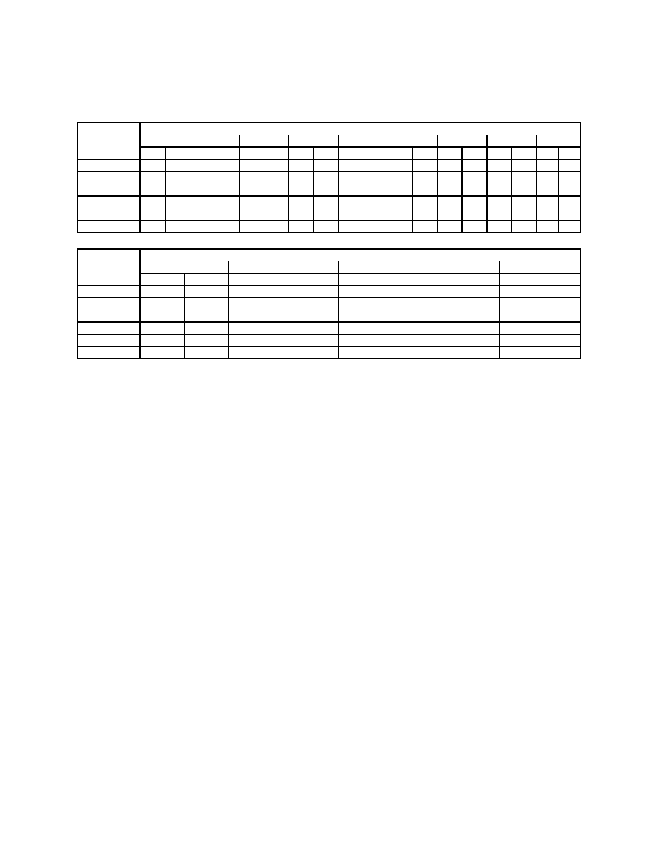
SBFC Standard Dimensions Cont’d.
Dimensions
Model A B C D E F G H J
number in. cm in. cm in. cm in. cm
in. cm
in. cm
in. cm in. cm
in.
cm
SBFC600
48” 122 38” 97 49” 125 45”
115
38”
97
29”
74 58”
148 44” 112 32”
82
SBFC1000 48” 122 38” 97 49” 125 44”
112
38”
97
29”
74 58”
148 44” 112 32”
82
SBFC1500 47” 120 38” 97 42” 107 46”
117
33”
84
20”
51 57”
145 42” 107 24”
61
SBFC2000 59” 150 38” 97 48” 122 46”
117
39”
99
20”
51 66”
168 54” 137 24”
61
SBFC3500 69” 176 47” 120 61” 155 62”
158
44”
112
20”
51 78”
199 63” 160 24”
61
SBFC5000 89” 226 51” 130 70” 178 63”
160
45”
115
13”
33 89”
226 73” 186 17”
43
Dimensions
Model
Air inlet/outlet dia. 3-way regulating valve Water outlet dia. Water inlet dia.
Drain dia.
number
in.
mm
dia. inches NPT
inches NPT
c
inches NPT
inches NPT
SBFC600 10”
254
mm
¾”
1”
1”
¾”
SBFC1000 10”
254
mm
1”
1¼”
1¼”
¾”
SBFC1500 14”
356
mm
1¼”
1½”
1½”
¾”
SBFC2000 14”
356
mm
1½”
2”
2”
¾”
SBFC3500 16”
407
mm
2”
2½”
2½”
¾”
SBFC5000 18”
457
mm
2”
2½”
2½”
¾”
c Customer is responsible to convert measurements to metric. Multiply inches by 25.4 to convert to mm.
Note: Allow a clearance of 48” (1.3 m) on each side of the blown
film cooler to permit access to the filter.