0 electrical installation, 0 calibration – Setra System Setra Model 206 User Manual
Page 4
3
4
3.0 Electrical Installation
The model 206 is available in the following electrical terminations:
• 2 foot cable (additional length available)
• 3-screw terminal block
• Hirschmann connector
• 1/2” conduit
3.1 Voltage Output Units
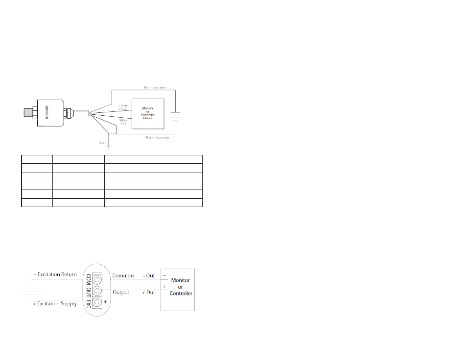
Wiring for cable, Hirschmann and conduit model 206 transducers with voltage
output is as follows:
Cable & Conduit Hirschmann Pin Designation Connection to electrical system
Red
#1
+Excitation; connect to 12-28 VDC power supply.
Green
#3
+Output; connect to controller or monitor.
White
#2
- Output; connect to controller or monitor.
Black
#2
-Excitation; connect to return of 12-28 VDC power supply.
Shielding
#4
Connect to system or earth ground.
Note 1: Model 206 can be wired as a three wire device by connecting -output and –excitation and shield to a common
ground. However, accuracy will be reduced because of voltage drops in the leads.
Note 2: Mating Hirschmann connects #GDM3009J, Hirschmann #932214-100 with GDM3-16 Hirschmann Gasket
#731531-002 are not provided by Setra Systems, unless ordered separately as an option.
V
oltage output Model 206 with a 3 screw terminal block have excitation, out-
put and common termination pouts clearly marked, wiring is as follows.
3.2 Current Output Units
Current output model 206 are true 2-wire, 4-20 mA current output devices
and deliver rated current into an external load of 0-800 Ω. Cable termina-
tion models have a 2-wire cable where red is positive and black is negative.
On the Hirschmann connecter, pin 1 is positive; pin 2 is negative and pin 4
is the ground/shield. Terminal block units have outputs label + for positive
and – for negative, the center terminal may be used for shielding.
Note: All 4-20 mA current output units are designed to have current flow in one direction only- PLEASE OBSERVE
POLARITY. We suggest that the electrical cable shield be connected to the system’s loop circuit ground to improve
electrical noise rejection.
4.0 CALIBRATION
Every model 206 is factory calibrated and should require no field adjust-
ment. Whenever possible, any zero and/or span offsets should be corrected
by software adjustments in the user’s control system. However, both zero
and span adjustments are accessible by removing the pan head screws and
turning the zero and span potentiometer screws inside. Pan Head screws
should be replaced after adjustment to maintain enclosure rating.
Voltage output units are factory calibrated into a 50 KΩ load. Voltage units
are operable into a 5000 Ω load or greater. The zero factory setting is ±50
mV.
Current outputs units (4-20 mA) are factory calibrated with a 24 VDC loop to
supply voltage and a 250 Ω load. The zero factory setting is ±0.08 mA. The
span (full scale) factory settings is ±0.16 mA. Zero and span adjustment are
approximately ±1.0 mA.