Setra System Model 204D User Manual
Page 4
Electrical Information for Optional ±15 VDC (Option 622) and ±24VDC (Option 621)
Excitation Pressure Transducers
Note: Any figures in parentheses ( ) pertain to the ±24 VDC excitation units only.
Connections
Cable Lead
Function
Note: Other leads in the
White
+15 (+24) Positive Excitation
cable are not used for
Black Power Supply Ground
electrical Option 621 and 622
Violet
- 15 (-24) Negative Excitation
unless the transducer has been
Yellow
Positive Output
wired for Remote Control (see Remote
Brown
Negative Output
Instructions)
Shield Case
Electrical - Electrical Option 622 permits operation from a ±15 VDC and electrical Option 621
permits operation from a ±24 VDC supply (common return grounded), and provides you with
the negative signal output lead also at the common ground potential. Thus many transducers
can be operated from one power supply into single-ended loads. Circuit is reversed voltage
protected for at least 5 minutes. Internal transient suppression network is provided for short
duration transients to 150 volts.
Grounding - For general usage and best results (lowest noise) grounding of the shield/case
to the black lead is recommended.
Power Supply Advice - This transducer has been designed to operate from a dual ±15 VDC
(±24 VDC ) source. Stated another way, the supply is a 30V (48V) center tapped supply. The
±15 V (±24 V) is 15 V (24 V) above the common power return lead, and the - 15 V (- 24 V) is 15
V (24 V) below the common power return lead.
All three power leads must be connected. The transducer will not function if just the +15 V
(+24 V) and
-15 V (-24 V) leads are connected to the power source.
To avoid circuit damage due to excessive voltage, the positive supply voltage should be held
within the range of +15 V to +20 V (+22 V to +30 V), and the negative supply voltage should
be held within the range of -10 V to -20 V (-10 V to -24 V).
Note on long cable use:
In some instances, use of long cables (several hundred feet length) may introduce enough
cable capacitance into the circuit to cause output oscillations. If encountered, this oscillation
may be eliminated by connecting a 100 ohm resistor (1/8th watt or larger) in series to each
of the output leads at the end of the 2 foot transducer cable. These series resistors, of course,
add to the output resistance.
Electrical Information for 4 to 20 mA Pressure Transducers
Electrical - The circuit is designed to operate as a true two-wire 4 to 20 mA pressure transducer.
Connection
The Setra 4 to 20 mA transducer has two electrical leads. These may be connected for current
flow in either direction, without change in performance or damage. We suggest that the electri-
cal cable shield be connected to the system loop circuit’s ground, thereby improving electrical
noise rejection.
4
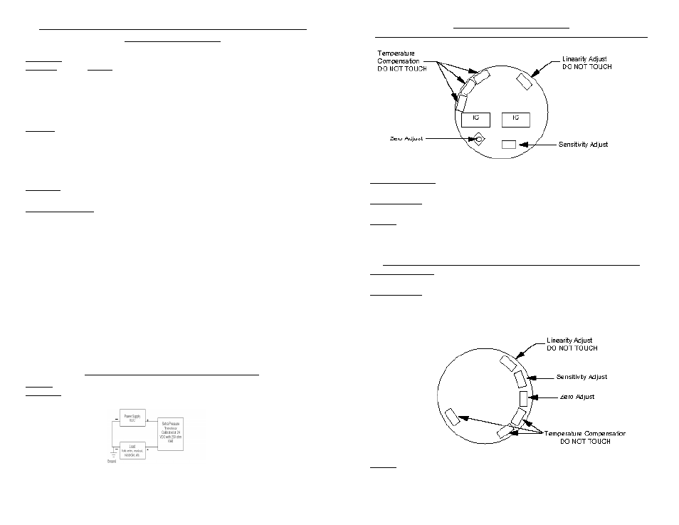
Adjustments for Zero and Sensitivity
Adjustments for Voltage Output Pressure Transducers (cover must be removed)
Caution: TURN OFF EXCITATION POWER DURING COVER REMOVAL OR REPLACEMENT
Zero Pressure Output - Can be adjusted to zero by potentiometer as shown in diagram. Unit
factory - adjusted to zero output (±10 mV for Model 204 and ±20 mV for Model 239).
Sensitivity (span) - Can be adjusted by potentiometer as shown on outline diagram. Unit fac-
tory - adjusted to order specifications.
Linearity - DO NOT TOUCH - Factory adjusted for best linearity. Touching any adjustments other
than zero output or sensitivity may necessitate recalibration.
Note: Sensitivity (span) adjustment is not recommended unless a primary pressure standard
(dead weight tester, etc.) is available for use as a reference.
Adjustments for Current Output Pressure Transducers (cover must be removed)
Zero Pressure Output - Zero output can be adjusted ±0.2 mA about the nominal 4 mA. The zero
adjustment is the potentiometer shown in the diagram. Changing zero will not change span.
Sensitivity (span) - Sensitivity can be adjusted approximately ±5 mA from the nominal 16 mA
full scale span. The sensitivity adjustment potentiometer is located as shown in the diagram
and may be adjusted without affecting linearity calibration.
Linearity - DO NOT TOUCH - Factory adjusted for best linearity. Touching any adjustments other
than zero output or sensitivity may necessitate recalibration.
Note: Sensitivity (span) adjustment is not recommended unless a primary pressure standard
(dead weight tester, etc.) is available for use as a reference.
5