Guidelines for rs-485 wiring (hf45), Cable grip and cable specifications, Wiring – ROTRONIC HF4 User Manual
Page 15: E-m-hf4-v1_22
E-M-HF4-V1_22
Rotronic AG
Bassersdorf, Switzerland
Document code
Unit
HygroFlex HF4 Humidity Temperature
Transmitters: User Guide
Instruction Manual
Document Type
Page 15 of 29
Document title
© 2009-2011; Rotronic AG E-M-HF4-V1_22
Lightning protection
Cabling in areas with a risk of lightning requires a lightning protection. For cabling underground in between
buildings, we recommend the use of special fiber optic cables. If this is not possible, use copper cables that
are suitable for underground installation.
6.2 Guidelines for RS-485 wiring (HF45)
See document E-DV04-RS485.01: RS485 Network Installation and Start-up Guidelines
6.3 Cable grip and cable specifications
The HF4 is
supplied either with one M16 sealing cable grip or with a ½” conduit adapter. The M16 cable grip
provides effective sealing only with cables having the proper outside diameter. Preferably, use a cable with an
outside diameter of 6 to 7 mm (0.236 to 0.275 inch) with 18 AWG wires.
6.4 Wiring
6.4.1
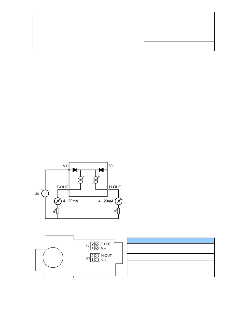
HF42: 2-wire, loop powered transmitter
Electrical diagram
The maximum permissible cable length connecting
the HF42 to other devices is determined by the total
resistance resulting from the addition of the cable
resistance and that of the devices connected in series
with the unit. This resistance should not exceed 500
ohms.
Terminal block diagram
Note: connect the + of the power supply to only one of the V+ terminals. The two terminals marked V+ are
internally connected.
Terminals
Description
K2-2: T-OUT
Temperature output (+)
OUT-2
K2-1: V+
Power supply: 10…28 VDC (+)
K1-2: H-OUT
Relative humidity or dew point (+)
OUT-1
K1-1: V+
Power supply: 10…28 VDC (+)