Installation of the hf4 type w (surface mount), E-m-hf4-v1_22 – ROTRONIC HF4 User Manual
Page 13
E-M-HF4-V1_22
Rotronic AG
Bassersdorf, Switzerland
Document code
Unit
HygroFlex HF4 Humidity Temperature
Transmitters: User Guide
Instruction Manual
Document Type
Page 13 of 29
Document title
© 2009-2011; Rotronic AG E-M-HF4-V1_22
Mounting hardware
Part AC5005 is a flange with compression fitting that is designed to hold the probe of
the HF4 type D when mounted through a wall (see Accessories). The HF4 does not
require any additional support. The AC5005 allows easy installation and removal of the
HF4.
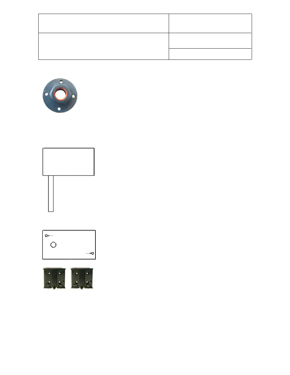
5.4 Installation of the HF4 type W (surface mount)
Mounting position of the enclosure
Mounting hardware
Method 1: The HF4 is supplied with 2 screws, 2 drywall anchors and two
rubber washers. The base of the enclosure has 2 screw-wells (see drawing)
that are normally closed at the bottom. Use the template provided with the HF4
to drill mounting holes in the wall and insert the drywall anchors. Place a
rubber washer on each screw. Insert a screw in each well and push to open
the bottom of the well.
Method 2: When a DIN-rail
(35 mm / 1 3/8 “) is available use part AC5002 (not
included). This is a DIN-rail mounting kit consisting of 2 clamps that attach to
the back of the enclosure with the screws provided.
Horizontal:
HF42, HF43 and HF45 type W