E-m-hf3-v1_22 – ROTRONIC HF3 User Manual
Page 17
E-M-HF3-V1_22
Rotronic AG
Bassersdorf, Switzerland
Document code
Unit
HygroFlex HF3 Transmitters and Thermo-
hygrostats: User Guide
Instruction Manual
Document Type
Page 17 of 27
Document title
© 2009-2011; Rotronic AG E-M-HF3-V1_22
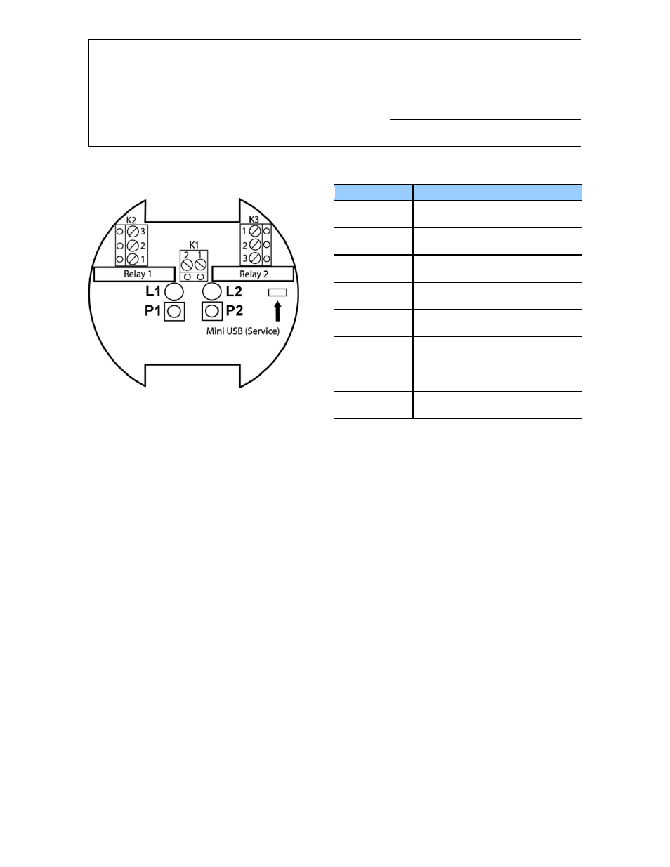
Terminal block diagram for type D and W
L1 : LED for relay 1 (lit when relay is energized)
L2 : LED for relay 2 (lit when relay is energized)
P1 : Set point adjustment potentiometer for relay 1
P2 : Set point adjustment potentiometer for relay 2
Note: the parameter (relative humidity, temperature, dew or frost point) corresponding to each relay can be
changed with the HW4 software.
6.3.4
Grounding (HF32, HF33 and HF34)
We generally recommend grounding the (-) side of the power supply, especially if the electronics will be
subjected to a low humidity environment (35 %RH or less).
Terminals
Description
K1-1
Power supply: 15…40 VDC (+)
or 12…28 VAC (Phase)
K1-2
Power supply (-) or neutral / ground
K2-1
Relay 1: humidity. Normally closed
K2-2
Relay 1: humidity. Common
K2-3
Relay 1: humidity. Normally open
K3-1
Relay 2: temperature. Normally
closed
K3-2
Relay 2: temperature. Common
K3-3
Relay 2: relative temperature.
Normally open