Installation – PATLITE FV-127JP User Manual
Page 7
- 7 -
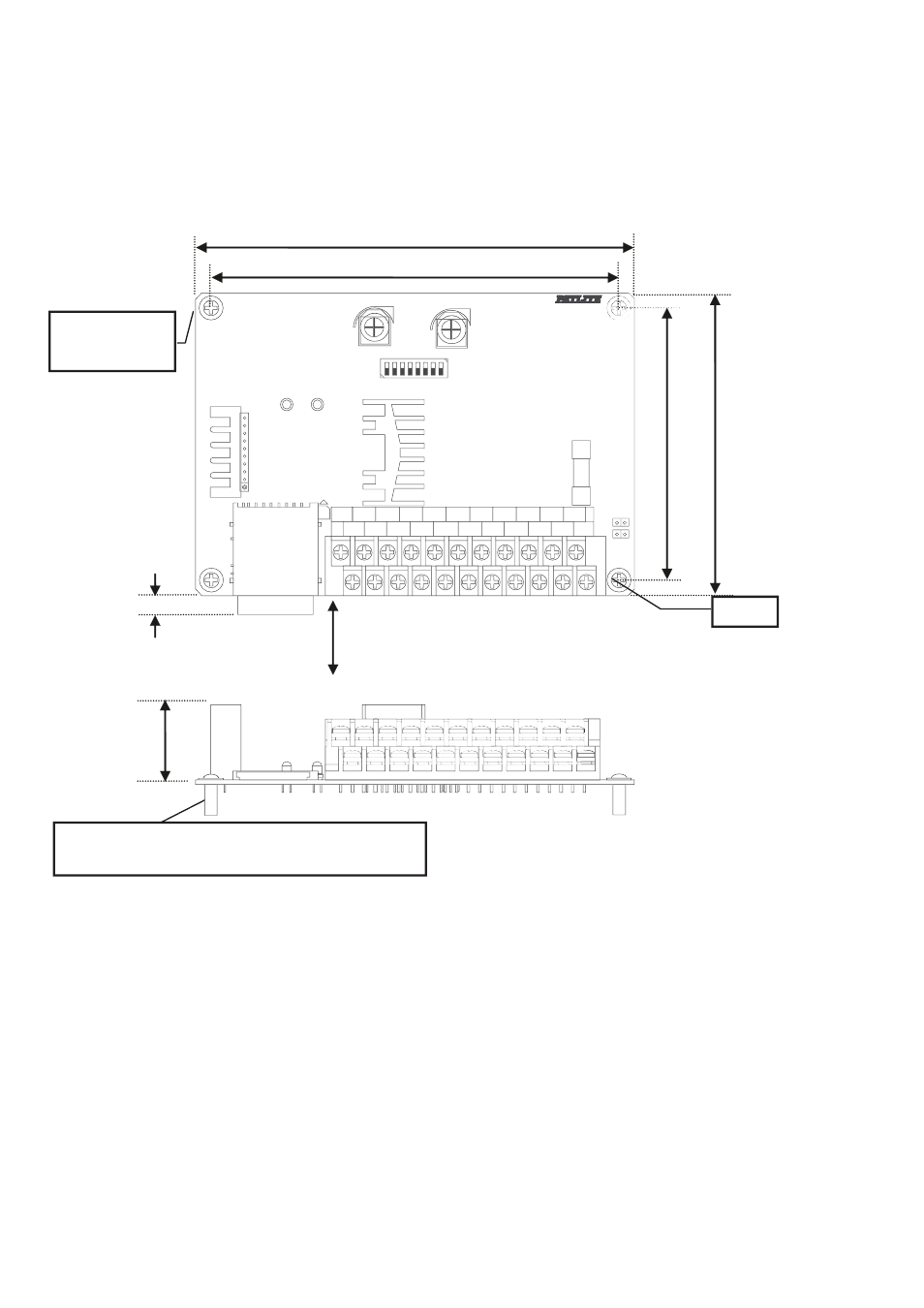
4. Installation
Use M3 screws and PCB spacers (not included) when installing the PC Board.
*
Recommended Spacer Size: 10mm
(Use metal spacer when grounding via the FG Hole)
For dimensions ( ☞ Refer to pg. 38 [Outer Dimensions])
DEC2
DEC1
/VOL
CH1
CH2
COM
SP-
SP+
AUX-
CH3
CH4
AUX+
BUSY-
CH5
CH6
BUSY+
24V
CH7
STB
0V
FG
CLR
STOP
90
100
144
134
6 (Insersion Gap)
Ensure enough clearance is made for
the SD Card (W:24mm L:32mm) to be
inserted and removed
Max. 28
[mm]
4-M3
Recommended
Torque: 0.3 N・m
FG Hole