3 electrical connection – NORD Drivesystems BU0100 User Manual
Page 21
NORDAC SK 160E
BU 0100 GB
Technical Modifications Reserved
21
4.3 Electrical connection
Power cable:
The system connection shall be performed with a cable of sufficient cross-section (max.
4 mm
2
).
Control unit:
5-pole plug with screw terminals 1.5 mm
2
(electrically separated from the system
potential)
PTC resistor/brake: 3 x 2-pole screw terminals with 1.5 mm
2
(on system potential)
Cable entry:
The following are available: 1 x M25 and 1 x M16 and 1 x M12. The 1 x M12 screw plug
may already be reserved by the brake connection and the M16 by the optional M12 plug.
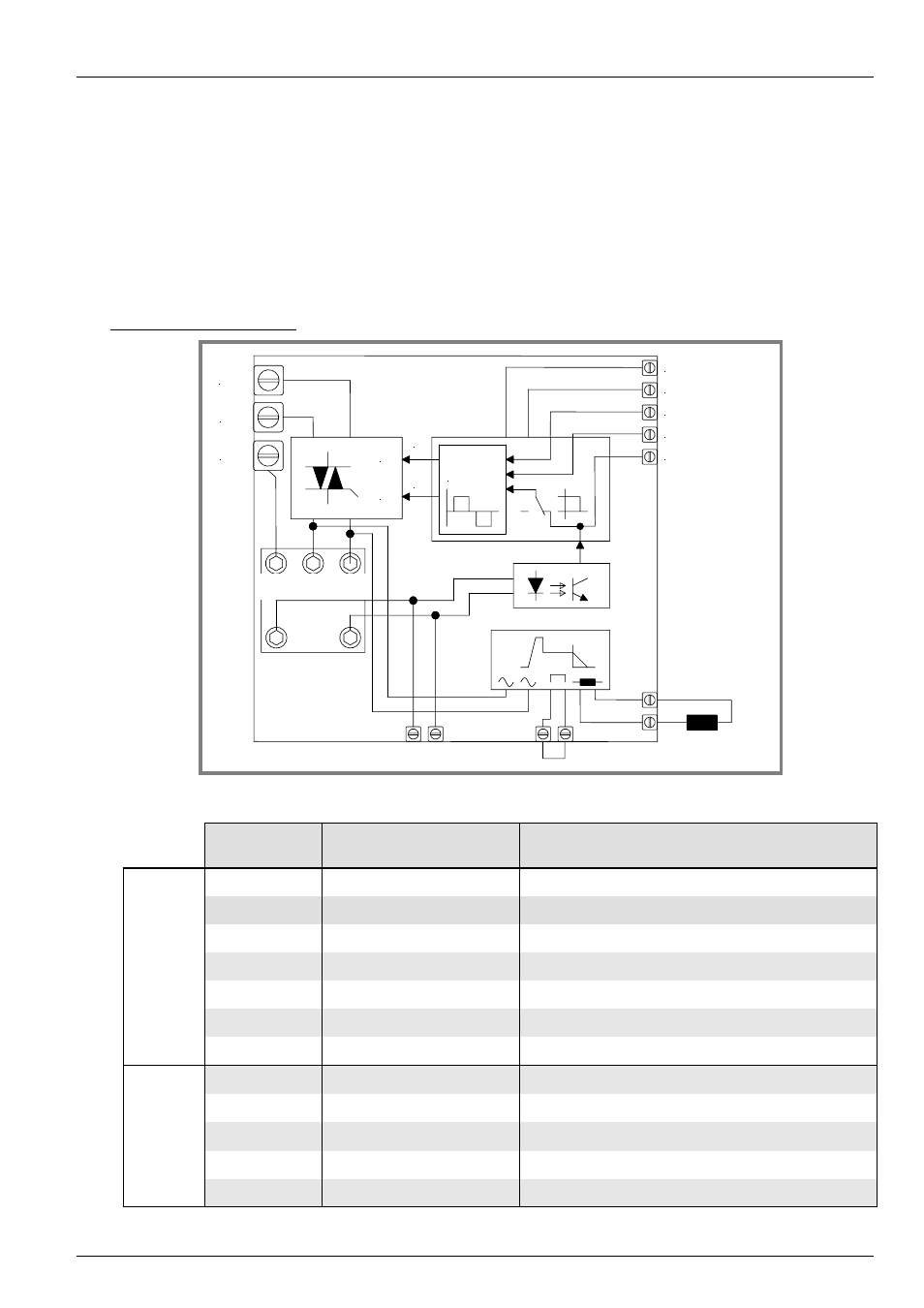
Principle circuit diagram:
+24V DC
RUN-LEFT
Bremsspule
Kaltleiter oder
Temperaturwächter
Brücke für langsames Abschalten
Schaltlogik
Reversier-
steuerung
RUN-RIGHT
Kaltleiter oder Temperaturwächter
OK
GND
L3
L2
L1
2x
2x
L
R
Motorklemmen
Terminal
Function
Data
Power unit
(Syst
em p
o
tent
ia
l)
L1, L2, L3
System connection
4 mm
2
, (200) 380...480 V, 50...60 Hz
PE
Housing ground
4 mm
2
[L]
Bridge L
1.5 mm
2
[BR-]
Brake coil
1.5mm
2
, (105) 180V DC … 205V DC, max. 0,5A
[BR+] Brake
coil
1.5mm
2
, (105) 180V DC … 205V DC, max. 0,5A
[38] Temp1
Temperature probe
1.5mm
2
[39] Temp2
Temperature probe
1.5mm
2
Control unit
(Elect
rically
sepa
ra
ted
)
[46] GND
Reference potential
1.5 mm
2
, 0 V
[45] +24 VDC
Supply voltage 24 V
1.5 mm
2
, 15...30V, 50 mA
[B1] OK
Feedback, operational
1.5 mm
2
, 15...30 V, max. 50 mA
[22] RUN-R
Release signal - right
1.5 mm
2
, 15...30 V, ca. 2 mA
[23] RUN-L
Release signal - left
1.5 mm
2
, 15...30 V, ca. 2 mA
Motor terminals
PTC resistor or
temperature
control
Brake coil
Bridge for gradual switching off
PTC resistor or temperature control