Information, Field bus systems – NORD Drivesystems MI0300 User Manual
Page 27
Power and and control terminal connection
27
Field bus level
PROFIBUS DP
System bus level and digital inputs
Digital outputs
24V
PB B
IN
PB A
IN
0V-B
RTS
24V
(as
for 1)
24V
(as
for 1)
0V
GND
0V
GND
DIN 1
0V
GND
24V
(as
for 1)
DIN 2
0V
GND
24V
(as
for 1)
24V 2
DO 1
0V 2
1
3
5
7
9
11
13
15
17
19
21
23
25
27
29
31
33
35
2
4
6
8
10
12
14
16
18
20
22
24
26
28
30
32
34
36
24V
(as
for 1)
PB B
OUT
PB A
OUT
0V-B
(as
for 8)
+5V B
24V
(as
for 1)
Sys +
Sys -
0V
GND
DIN 3
0V
GND
24V
(as
for 1)
DIN 4
0V
GND
24V
(as
for 1)
0V 2
DO 2
0V 2
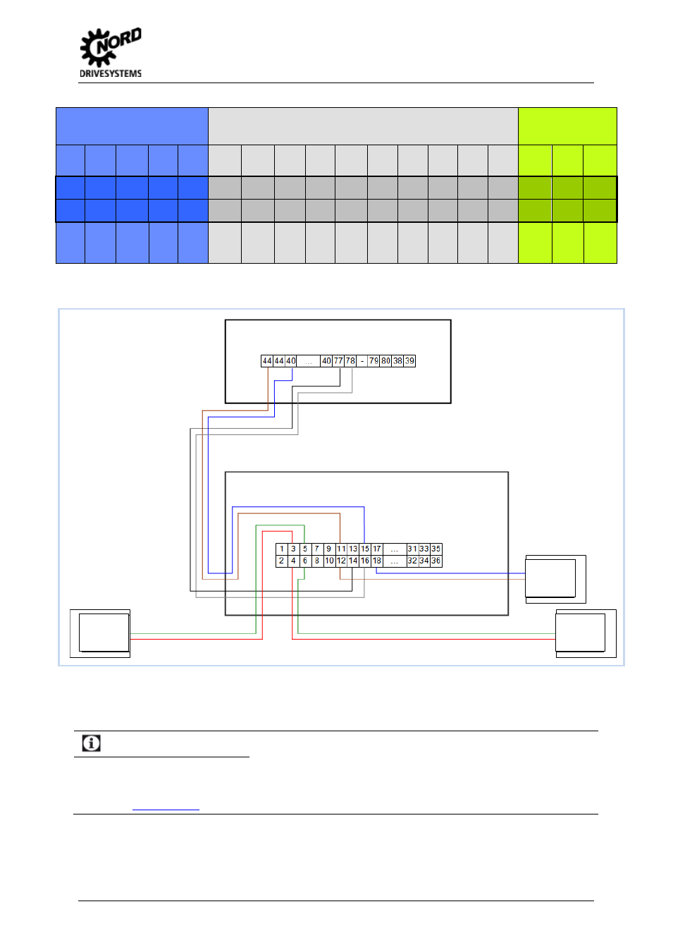
Fig. 21: Control terminals of technology option SK TU4-PBR-(C) for SK 2xxE
Fig. 22: Connection example for technology option SK TU4-PBR-(C) for SK 2xxE
Information
Field bus systems
In this document a detailed description is given for the field bus systems AS interface and Profibus DP as
examples for all field bus systems which are available from NORD. For information about the DeviceNet and
CANopen technology options please refer to the relevant manuals (BU0080, BU 0060, BU 0200, or BU 0260 and
BU 0280).
SK 205E…-Connection unit (SK TI4…)
SK TU4-PBR…-Connection unit (SK TI4-TU-BUS)
Voltage
Source
24V DC
PROFIBUS
Subscriber
X-1
PROFIBUS
Subscriber
X+1
Potential level: field bus
Potential level: system bus
Potential level: DOs