Dwyer ULT User Manual
Page 4
24 VDC
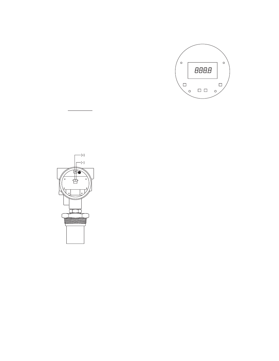
INDEX
ENTER
UP DOWN
figure 4: electrical Wiring Diagram
figure 5: Display and programming Buttons
SeTUp & CaLiBRaTiOn
Four buttons are provided for all setup and calibration opera-
tions. All settings are stored in nonvolatile memory so they will
not be lost if the power is removed.
Where VPS is the power supply voltage.
RMAX =
VPS - 18.0
20mA
power Supply
The transmitter requires a minimum of 18 Volts DC at its con-
nection for proper operation, and a maximum of 28 Volts.
Choose a power supply with a voltage and current rating suffi-
cient to meet this power specification under all operational con-
ditions. If the supply is unregulated, make sure that the output
voltage remains within the required voltage range under all
power line conditions. Ripple on the supply should not exceed
100 mV.
Loop Resistance
The maximum allowable loop resistance is dependent on the
power supply voltage. The maximum loop voltage drop must not
reduce the transmitter voltage below the 18 Volt minimum. The
maximum loop resistance can be calculated using the following
equation:
KeY fUnCTiOnS
inDeX
Pressing the inDeX button advances the display to the next
menu item.
enTeR
Pressing the enTeR button for approximately two seconds will
end operating mode and enter programing mode. In program-
ming mode press the enTeR button will store the value of menu
items once they are changed to a new value.
Up
Pressing the Up button increments a value in programming.
DOWn
Pressing the DOWn button decrements a value in programming.
Up & inDeX
Pressing the Up and inDeX simultaneously will allow faster
increments in a value for programming.
DOWn & inDeX
Pressing the DOWn and inDeX simultaneously will allow faster
decrements in a value for programming.