Dwyer ULT User Manual
Page 3
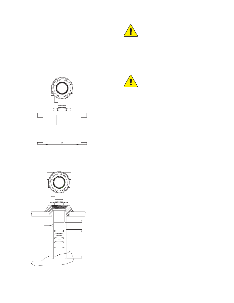
MOUnTinG fiTTinG
Fittings should be selected that minimize the installation height
of the transmitter so that mounting hardware does not interfere
with the acoustic signal. If the installation does require a riser
then the transmitter may be elevated up to 12˝ (30 cm) in a 6˝
(15 cm) diameter riser, 8˝ (20 cm) in a 4˝ (10 cm) diameter riser,
and 3˝ (7.6 cm) in a 2˝ (5 cm) diameter riser, see Figure 2. A
stand pipe may be used to dampen turbulence or separate sur-
face foam. Use a minimum 3˝ diameter pipe and cut to the
desired length of the transmitter span with a 45° notch at the bot-
tom. A ventillation hole needs to be created at the top of the pipe
within the 8˝ (20 cm) blind zone, see Figure 3.
HEIGHT
INNER
DIAMETER
R
IS
E
R
figure 3: Stand pipe Mounting
figure 2: Riser Mounting
VENTILLATION HOLE
BLIND ZONE
8 [203.20]
OPERATIONAL
RANGE
LOWEST LIQUID LEVEL
ø3 [76.20] MINIMUM
eLeCTRiCaL COnneCTiOn
CaUTiOn: Do not exceed the specified supply volt-
age rating. Permanent damage not covered by the
warranty may result. This unit is not designed for AC
voltage operation.
nOTe: Installation must be made in accordance with local codes
and regulations. When fishing wire through the conduit connec-
tion do not allow the wire to touch or press on components on
the boards. Damage to the circuitry may result. Make sure that
the wire is routed so it will not interfere with the calibration
switches.
CaUTiOn: Hazardous area Use: Plug any
unused conduit openings. Plug must engage a
minimum of 5 threads. Use a conduit seal within
18˝ (45.7 cm) of conduit entry. Disconnect power
before opening, servicing, programming, installing,
or removing.
The ULT provides two 1/2˝ NPT female ports for conduit con-
nection. The conduit connection must be made such that con-
densation is not allowed to enter the sensor housing. If neces-
sary install a conduit breather drain in a separate conduit body
to prevent buildup of moisture. If nonmetallic conduit is used the
protective ground may be connected to the internal ground con-
nection screw.
The ULT transmitter is designed as a two wire 4-20 mA device.
Connection to the board is through a two pin terminal block. The
circuitry is polarized so the positive must be connected to termi-
nal 1 and the negative must be connected to terminal number 2.
It is recommended that shielded twisted pair wire be used if the
potential exists for interference from external noise sources.
Ground the shield at the case using the internal ground screw
and leave the other end of the shield open. Do not use the
shield as one of the current loop conductors.