Figure 1: unsuitable mounting locations – Dwyer ULT User Manual
Page 2
TEMPERATURE/PRESSURE DERATING
TEMPERATURE °C
UNACCEPTABLE
RANGE
O
P
E
R
A
T
IN
G
P
R
E
S
S
U
R
E
P
S
I
ACCEPTABLE
RANGE
40
30
20
10
0
-40 -20 0 20 40 60 80
OpeRaTinG pRinCipLe
Ultrasound is sound with a frequency greater than the upper limit
of human hearing; approximately 20 kilohertz. The ULT contains
an ultrasonic transducer and a temperature sensing element.
The ultrasonic transducer transmits ultrasound wave pulses
through air directed towards the material of which the level is
desired. The ultrasound waves then reflect off of the material as
an echo and travel back to the transducer. The level of the
material is determined by the transit time of the ultrasound wave
pulse from the sensor to material and for the echo to come back
to the sensor. The speed of sound through air is sensitive to the
air temperature. The ULT uses the temperature sensing element
to compensate for air temperature changes.
The ULT incorporates patented surface processing technology
and adaptive signal processing. Surface processing technology
filters out all signal obstructions that may be in the tank creating
an effecting beam diameter of only 3˝ (7.6 cm). This beam diam-
eter is a straight column and not cone shaped like competitor
units. Adaptive signal processing continuously optimizes sensor
power, output filtering, and environmental noise rejection.
inSTaLLaTiOn
Unpacking
Remove the ULT from the shipping carton and inspect for dam-
age. If damage is found, notify the carrier immediately.
Materials
The ULT may be used to detect level of a variety of materials.
Since the sensing technology is non-contact it is well suited for
corrosive, coating, slurry, or sticky media. The hazardous
approval rating also makes the unit ideal for use with hazardous
rated applications. Please see the specifications section for haz-
ardous approval classifications.
Mounting Location
• The process temperature and ambient temperature must
be within the specified limits.
• The probe must be located away from tank inlets or
chutes where material may fall on the probe during
filling or emptying.
• The probe must be located at least 3˝ (7.6 cm) away
from the tank side wall.
• The probe cannot be used in vacuum applications.
• The probe must be installed vertically and perpendicular
to the media surface.
• Make sure the covers are accessible to allow for
programming, wiring, and ability to see the display.
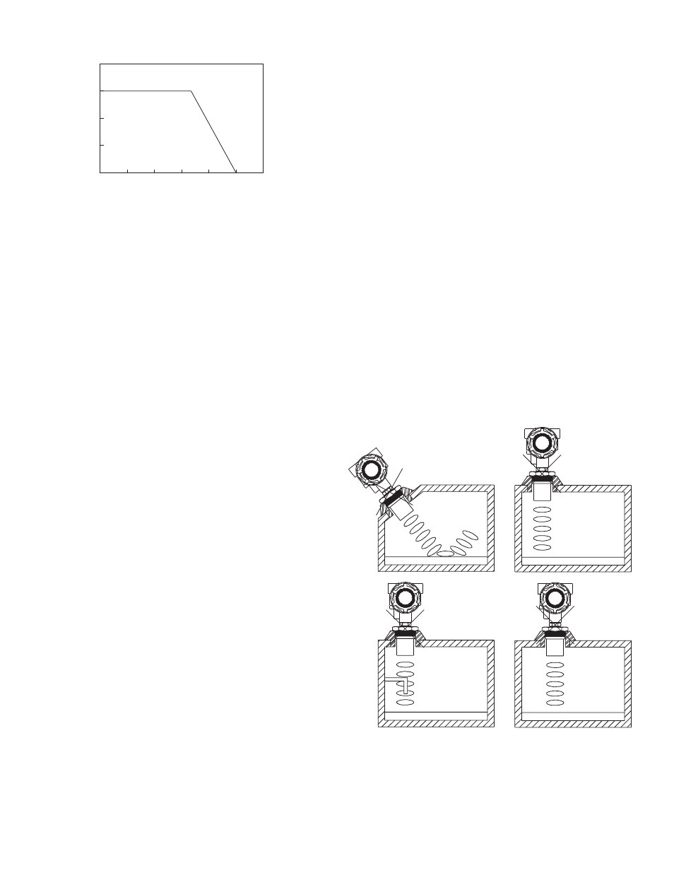
DO NOT INSTALL
WITHIN THREE INCHES
OF TANK SIDE WALL
DO NOT INSTALL
IN APPLICATIONS
WITH VACUUM
VACUUM
figure 1: Unsuitable Mounting Locations
DO NOT INSTALL AT
AN ANGLE RELATIVE
TO THE LIQUID
DO NOT INSTALL
WITH OBJECTS
IN THE BEAM