Dwyer SSM User Manual
Page 2
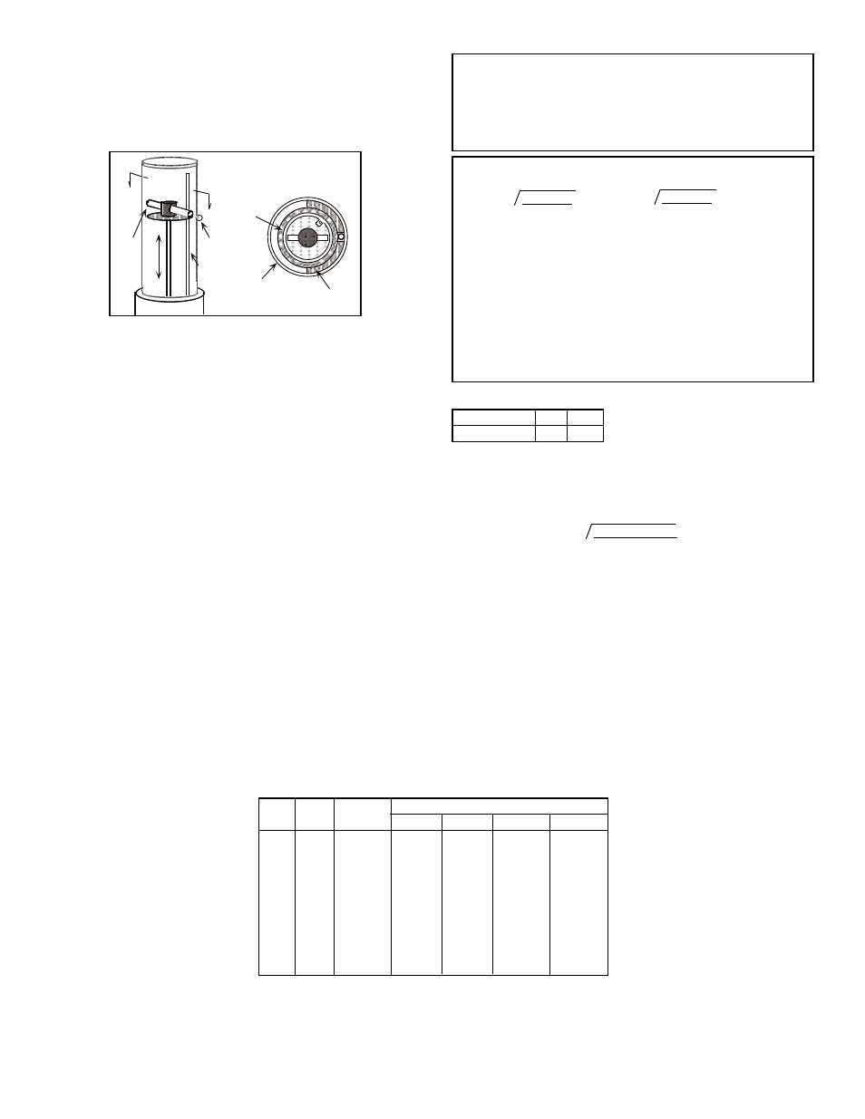
loosened to allow rotation of the carrier toward the desired scale
location. Re-tighten the screw (thread sealant is recommended), replace
magnet, and reassemble the meter (see “Assembly”). Verify that the ball
indicator has been “captured” by the magnet. If not, rotate the sight tube
(DO NOT twist on the edges of the plastic raceway assembly) until the
ball is “grabbed” by the float magnet.
STARTUP: System flow should be started with the bypass valve open
and meter inlet and outlet valves closed. After the system is operating,
open the meter inlet valve gradually to equalize internal pressure. Then
slowly crack meter outlet valve and wait for float to stabilize. Finally,
slowly open the meter outlet and/or flow regulating valve all the way and
close the system by-pass valve. AVOID SUDDEN SURGES THAT
CAUSE THE METER FLOAT TO SLAM INTO THE TOP OF THE SIGHT
TUBE! Although not essential, the meter sight tube should be filled to a
level above the float on liquid systems. The snorkel tube (present in most
standard models) allows escape of entrapped gases except for a small
pocket in the upper end which helps cushion hydraulic shock. To assure
proper filling and to flush any foreign particles from the meter, operate
the system at full flow briefly at startup.
ReaDinG fLoW
Read flow directly from the scale as the number nearest to the center of
the ball indicator.
coMpenSatinG foR SYSteM cHanGeS
To find the correct flow reading for a system whose fluid conditions vary
from those for which the meter is scaled, use the conversion equations
provided. The most practical method of applying the formulae is to
calculate a conversion factor for the new system condition and
multiplying the scale reading by that factor. In the problems to the right,
“Q’s” has been assigned a value of “1” to determine the conversion
factor. (Dwyer Instruments, Inc. can provide special scales at additional
cost for other fluids and/or units.)
SEC A-A, TOP VIEW
POLYCARBONATE
COVER
METAL
PRESSURE
TUBE
PHENOLIC
RACEWAY
A
A
MAGNET
BALL
INDICATOR
SNORKEL-
GUIDE
CORRECTING READINGS FOR NEW LIQUID CONDITIONS
Where:
Qa=Actual flow, GPM (or same units as scale)
Qs=Meter reading from scale, (scale units)
ps=Specific gravity of calibration liquid related to water in std.
atmosphere at 70˚F being 1.00
pa=Specific gravity of metered liquid, same base
ds=Density of calibration liquid, lbs/ft3
da=Density of metered liquid, lbs/ft3
pf=Specific gravity of meter float
df=Density of the meter float as per Table below
MaXiMUM fLoWS (WitHoUt effectinG accURacY)
foR UnDeRSiZeD pipeS connecteD DiRectLY to
fLoWMeteR inLetS
pipe
npS
1/4
3/8
1/2
3/4
1
1-1/4
1-1/2
2
2-1/2
3
Data
(iD)
2
0.132
0.243
0.387
0.679
1.100
1.904
2.592
4.272
6.096
9.413
MaX. *
GpM LiQ.
1.72
2.98
4.74
8.31
13.47
23.32
31.74
52.29
74.56
115.2
atMoS.
0.864
1.59
2.53
4.44
7.20
12.5
17.0
28.0
39.9
61.6
50 pSiG
3.80
7.00
11.1
19.5
31.7
58.8
74.6
123
176
271
100 pSiG
6.74
12.4
19.8
34.7
56.1
97.2
132
218
311
480
200 pSiG
12.6
23.2
37.2
64.9
105
182
248
408
582
804
MaX. ScfM aiR @ †
Data per Cameron Hydraulic Data. Based on 5 FPS max. liquid
velocity having no effect on flowmeters accuracy if the inlet pipe is
smaller than the meter connections.
SCFM=0.445 x (psig + 14.7) x (ID)
2
. Based on 20 FPS max. air
velocity having no effect on flowmeters accuracy if the inlet pipe is
smaller than the meter connections.
*
†
CAUTION: DO NOT OPERATE THE FLOWMETER ON A SYSTEM
EXCEEDING THE OPERATING LIMITS OF THE UNIT. WHEN
CHANGING OPERATING CONDITIONS, MAKE SURE THAT THE
NEW SYSTEM CONDITIONS ARE WITHIN THE FLOWMETER
OPERATING LIMITS, AND ALL WETTED MATERIALS ARE
COMPATIBLE WITH THE FLUID.
Qa = Qs
√
Ps(Pf-Pa)
Pa(Pf-Ps)
√
ds(df-da)
da(df-ds)
or Qa = Qs
fLoat Specific GRaVitieS/DenSitieS
Material
Stainless Steel
pf
8.05
df
501.1
EXAMPLE: Using a standard stainless steel meter scaled for water (ps
= 1.00), what is the conversion factor for an oil with a specific gravity of
0.85?
Thus, actual flow of the oil would be the observed scale reading times
1.096.
=1.096
Qa = 1.00
x
√
1.00 (8.05-0.85)
0.85 (8.05-1.00)
fiGURe 1