Dwyer PDWS User Manual
Page 2
Page 2
GeNeRal iNFORMatiON
The PDWS Series are impeller (or “paddlewheel”) insertion me-
ters designed for use with a wide variety of liquids in pipe sizes
1/2" to 8". Sensors are available in brass, 316 stainless steel,
PVC, and polypropylene. Bodies are machined from a solid rod
for maximum precision. High-quality jewel bearings and nickel-
bound tungsten carbide shafts are used for extreme low friction
and long life. Low-flow performance is good, although other
Dwyer Instruments Inc. flow meters are recommended where
extremely low flows are being measured.
The rotation of the rotor is detected by a non-drag Hall-effect
sensor. Output is a current-sinking pulse (square wave), which
can be sent long distances (up to 2,000 feet) without a trans-
mitter. This signal can be connected directly to PLC's, counters,
and computer cards, as well as a variety of Dwyer Instruments
Inc. controls and displays.
PDWS meters are ideal for chemical proportioning applications.
If no display is required, a simple divider such as the PWD
provides adjustable pump pacing. For rate and total display,
the Series RTI (loop powered) flow indicator can be mounted
directly on the Series PDWS meter, or remotely on a wall or
panel. The Series BAT blind analog transmitter can be used to
convert to a 4 to 20 mA output.
The Series PDWS require special fittings that ensure correct
depth placement in the pipe. Fittings come in a variety of ma-
terials for compatibility with specific applications. Tee fittings
are individually wet-calibrated at the factory and marked with
the K-factor (pulses per gallon). Saddle fittings must be field-
installed on the pipe and do not come wet-calibrated. K-factors
for saddles are based on factory-testing. Please see Series PWF
for appropriate fittings.
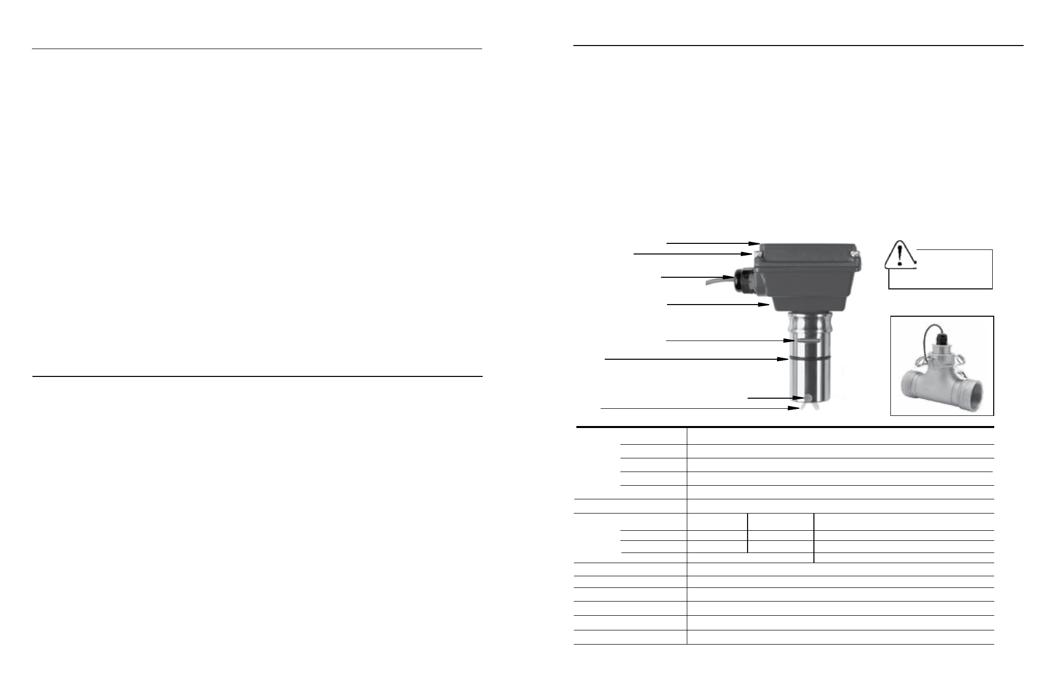
caution:
Clip(s)
must be installed
before use.
FeatuReS
Rotor
O-Ring
Retaining Slot (for U-Clip)
For easy installation at correct depth setting
Lower Housing (optional)
Cable-Seal Strain Relief
Housing Screw
(connect ground to one)
Cover or Optional Module
Jewel Bearings for superior low-flow performance
Page 3
table OF cONteNtS
General information
Features, Specifications ........................................................................................................Page 3
installation
Insertion Depth, Distorted Flows, Fitting Installation, Meter Installation, Positioning the Meter......................Page 4
Straight Pipe Recommendations .............................................................................................................Page 5
Full Pipe Recommendations ..........................................................................................................Page 6
connection Diagrams
RTI/BAT, Connecting to PLC's..............................................................................................................Page 7
Operation
Minimum Flow, Flow Range Table, Calibration (“K-Factor”), Field Calibration..................................................Page 8
Maintenance
Rotor Replacement, Signal Troubleshooting, Sensor Replacement .............................................................Page 9
Parts explosion
Parts List ......................................................................................................................................................Page 10
troubleshooting
Problems, Probable Causes, To Check, To Repair ..................................................................................Page 11
tableS aND DiaGRaMS
Specifications, Features ...............................................................................................................Page 3
Distorted Flows, Positioning the Meter .............................................................................................Page 4
Straight Pipe Recommendations .................................................................................................Page 5
Full Pipe Recommendations ...........................................................................................................Page 6
Connections Diagrams .......................................................................................................................Page 7
Flow Range Table, K-Factor Number on Tee Fitting, K-Factor Chart, Pressure vs. Temp Chart...................Page 8
Rotor and Sensor Replacement .............................................................................................................Page 9
Parts Explosion, Parts List ........................................................................................................................Page 10
Troubleshooting............................................................................................................................................Page 11
SPeciFicatiONS*
Brass, 316 Stainless Steel, PVC, or Polypropylene
PVDF
Nickel-bonded tungsten carbide (Ceramic optional)
Ruby jewel
EPDM (Fluoroelastomer optional)
GMR (Giant Magnetoresistive) Sensor
brass
316 SS
PVc or Polypropylene
(See Pressure vs. Temp. Chart)
200 PSI (14 bar)
250 PSI (17 bar)
175 PSI (12 bar) @ 75˚ F
Not Available
400 psi (28 bar)
Not Available
200˚F (93˚C)
130˚F (55˚C)
0.3 to 30 ft/s
+/- 1.5% of full-scale
Hall-effect current sinking pulse
6-24 Vdc, 2 mA
20 mA
#22 AWG, 3 Cond, 18' (maximum 2000’ run)
Materials Sensor body
Rotor
Shaft
bearings
O-Ring
Rotor Pickup
Maximum
Pressure
high Pressure
temperature
Flow Range
accuracy
Signal
Power
Maximum current
cable
*Specifications subject to change
high Pressure Model