2 electrical connection, Electrical connection – Dwyer MFS User Manual
Page 6
Installation of the flow sensor
6.2 Electrical connection
• Caution: Voltage Hazard!
Always de-energize the system before connecting the wires.
Warning:
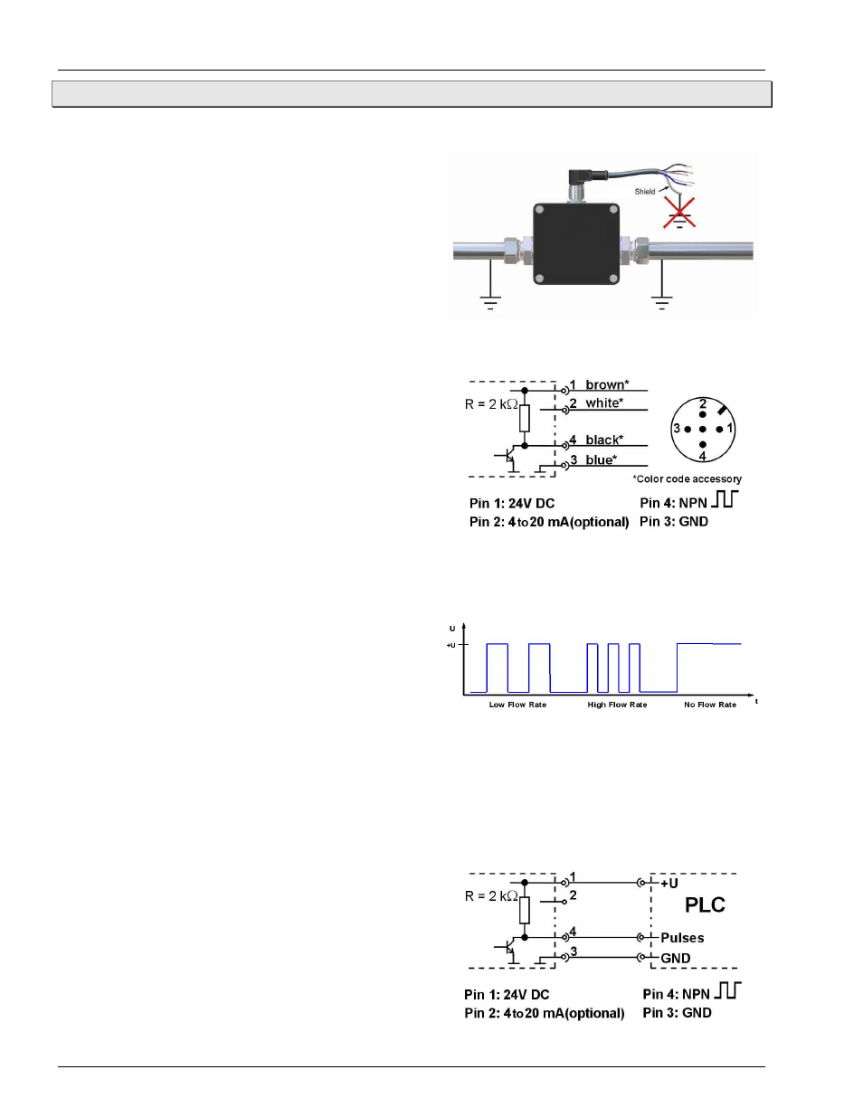
We recommend the use of shielded connecting cables
only. The shield should not be connected to ground. We
recommend to ground the pipes directly before and behind
the MFS (see Fig. 5).
We offer appropriate connecting cables with 4-pin cable
socket as accessories. The shield is connected with the
knurled nut. They are available in various lengths.
Electrical connection with 4(5)-pin connector M12x1:
ª
Screw the 4-pin contact box M12x1 onto the
connector.
ª
Tighten it with a tightening torque of max. 0.74 ft lb.
ª
Connect the connecting cables of the MFS (see
Fig. 6).
Important!
Do not connect Pin 5 (center pin)!
The output signal Pin 4 is a flow-proportional frequency signal (see Fig. 7). It represents a square-wave output
signal whose amplitude roughly corresponds to the supply voltage. The supply voltage and the output signal are
not galvanically isolated.
After switched on, the operating status is shown by a
multiple flashing of the LED. Throughout the operation, the
LED flash corresponds to the flow rate:
• No flow rate Ö no flashing.
• Low flow rate Ö slow flashing.
• High flow rate Ö fast flashing.
The optional analog output Pin 2 provides a flow proportional signal current of 4 to 20 mA. Please note the
maximum load of 250 Ω to GND.
Connection to an Programmable Logic Controller (PLC):
Most digital PLC inputs are designed for connection to PNP signals. The MFS has an NPN frequency signal with
an integrated 2kΩ pull-up resistor. Its signal current of ~12 mA is recognized as a signal by the current PLC.
Thus, operating a MFS with a PLC should not present any problems.
The frequency output of the MFS should be attached to a
digital input of the PLC.
Important! Please ensure that your PLC is able to process
the high frequencies of the MFS output signal.
ª
Attach the connecting cable of the MFS to the PLC as
illustrated in diagram 8.
Fig. 5: Ground the pipes
Fig. 6: Electrical connection
Fig. 7: Frequency output signal
Fig. 8: Control with PNP Input signal