Dwyer TFP-GV User Manual
Page 8
F-20-TFP-G, pg. 8 of 27
4.
Electrical Connections
CAUTION
: Incorrect wiring may cause severe damage to the
unit. Applying an AC voltage (115VAC or 230VAC) directly to
the unit will cause damage. Read the following instructions
carefully before making any connections.
a)
Overview
The TFP-GV Series provides a 0-5VDC output proportional to the volumetric
flow rate. This output may be connected to a display, data acquisition
system or voltmeter.
The TFP-GI Series features an integral display that provides a local flow
reading. These units also have a 0-5VDC analog output available. If
required, this may be connected to another display, data acquisition system
or voltmeter.
A stable D.C. power supply is required to operate the unit. The voltage and
current requirements depend on the configuration of the unit. Full details
may be found in the Specification section of this manual.
Connecting wires should be as short as possible to avoid voltage drops.
Twisted 2 pair conductor cable of a suitable gauge should be used if the
length of the power wires is to be longer than 1 meter (3.2 feet).
Units are supplied with an integral 4 pin connector. Connections to the unit
are made using a mating cable assembly or power adapter package as
detailed in the following sections. A connector pin and wire color cross
reference may also be found in Appendix F (Page 18) of this manual.
b)
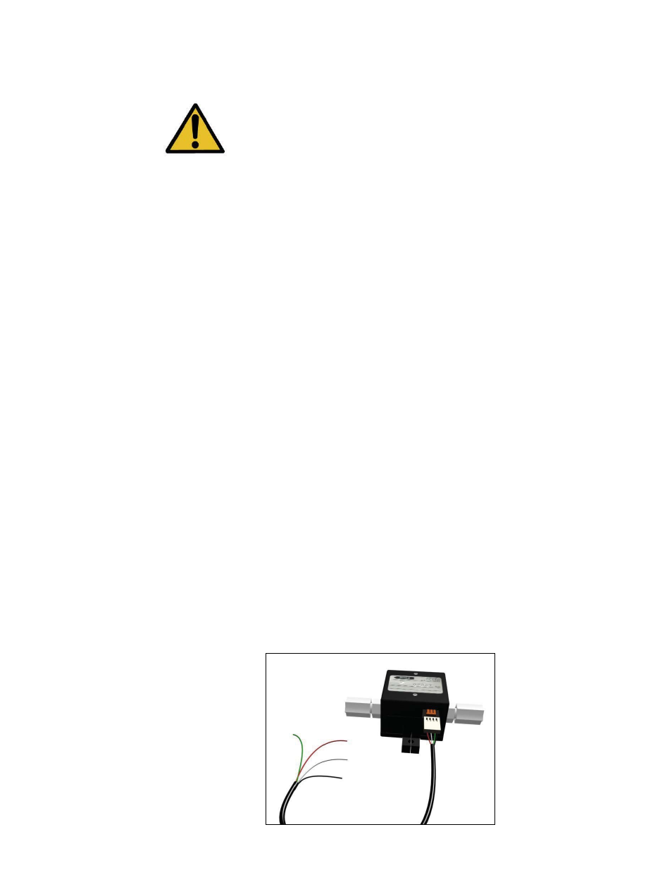
Connecting a Cable Assembly
The connector on the cable assembly should be pushed into the mating
socket on the sensor taking care to ensure that it is the correct way up.
Connecting the Cable Assembly
(All models similar)