Dwyer DMF User Manual
Page 8
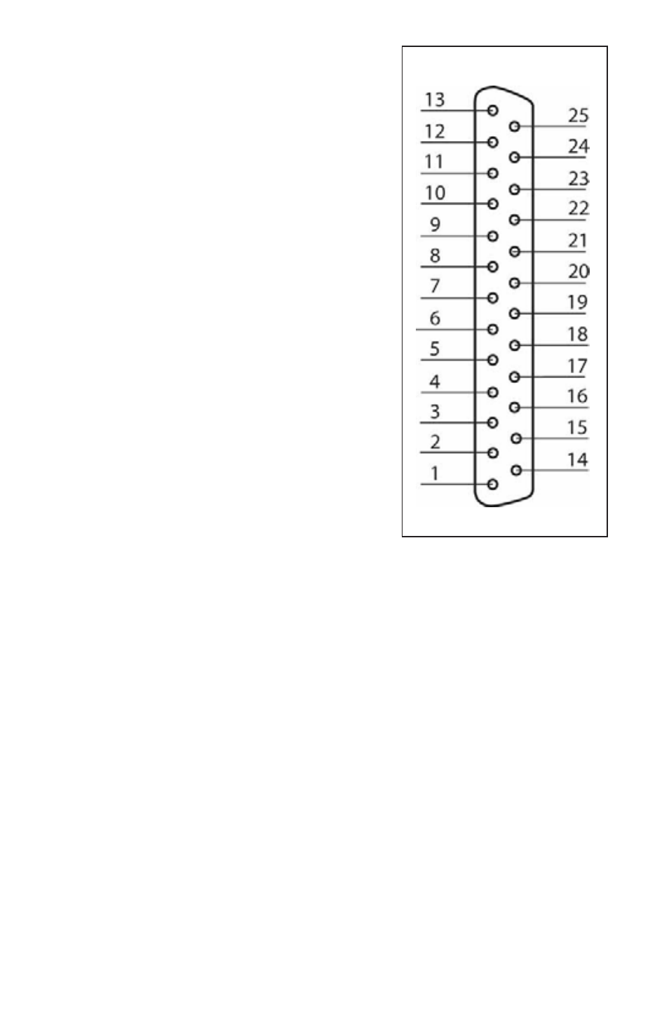
PIN FUNCTION
1
+15 VDC Power Supply
2
0-5 VDC Flow Signal (4-20mA Option)
3
0-5 VDC Set Point Input (4-20mA Option)
4
Force Valve Open Control
5
Force Valve Closed Control
6 (Reserved)
7 (Reserved)
8
Relay No. 1 - Common Contact
9
Relay No. 1 - Normally Open Contact
10
Relay No. 2 - Normally Closed Contact
11
RS485 (-) (Optional RS232 TX)
12 (No
Connection)
13 Chassis
Ground
14
-15 VDC Power Supply
15
Common, Signal Ground For Pin 2
16
Common, Signal Ground For Pin 3
17
(Optional) RS232 Common
18
Common, Power Supply
19 Common
20 Common
21
Relay No. 1 - Normally Closed Contact
22
Relay No. 2 - Common Contact
23
Relay No. 2 - Normally Open Contact
24
RS485 (+) (Optional RS232 RX)
25
Return for Pin 2 (Optional 4-20 mA Only)
FIGURE b-2, DMF 25 PIN "D" CONNECTOR CONFIGURATION
Important notes:
In general, "D" Connector numbering patterns are standardized. There are, how-
ever, some connectors with nonconforming patterns and the numbering sequence
on your mating connector may or may not coincide with the numbering sequence
shown in our pin configuration table above. It is imperative that you match the
appropriate wires in accordance with the correct sequence regardless of the par-
ticular numbers displayed on your mating connector.
Make sure power is OFF when connecting or disconnecting any cables in the system.
The (+) and (-) power inputs are each protected by a 500mA M (medium time-lag)
resettable fuse. If a shorting condition or polarity reversal occurs, the fuse will cut
power to the flow transducer circuit. Disconnect the power to the unit, remove the
faulty condition, and reconnect the power. The fuse will reset once the faulty con-
dition has been removed.
Cable length may not exceed 9.5 feet (3 meters).
5
ƽ