Dwyer GFM2 User Manual
Page 5
Flow Rates
Flow rates are stated for Nitrogen at STP conditions [i.e. 70°F (21.1°C) at 1 atm].
For other gases use the K factor as a multiplier from APPENDIX III.
5. OPERATING INSTRUCTIONS
5.1 - Preparation and Warm Up
It is assumed that the Digital Mass Flow Meter has been correctly installed and
thoroughly leak tested as described in section 2. Make sure the flow source is OFF.
When applying power to a flow meter within the first 2 seconds you will see on the
LCD display: the product name, the software version, and revision of the
EEPROM table (applicable for LCD option only).
Figure b-2: GFM2 First Banner Screen
Within the next 2 seconds, the RS-485 network address, the analog output settings,
and currently selected gas calibration table will be displayed (applicable for LCD
option only).
Figure b-3: GFM2 Second Banner Screen
After 2 seconds, the LSD display switches to the main screen with the following
information:
- Mass Flow reading in current engineering units (upper line).
- Totalizer Volume reading in current volume or mass based engineering units
(lower line).
Figure b-4: GFM2 Main Screen
During initial powering of the GFM2 transducer, the flow output signal will be
indicating a higher than usual output. This is an indication that the GFM2
transducer has not yet attained its minimum operating temperature. This condition
will automatically cancel within a few minutes and the transducer should eventually
indicate 0.
For the GFM2 transducer with LCD option: If the LCD diagnostic is activated, the
second line of the LCD will display the time remaining until the end of the warm
up period (Minutes:Seconds format) and will alternatively switch to Totalizer reading
indication every 2 seconds.
Figure b-5: GFM2 Main Screen During Sensor Warm Up Period.
5.2 Swamping Condition
If a flow of more than 10% above the maximum flow rate of the Mass Flow Meter
is taking place, a condition known as "swamping" may occur. Readings of a
"swamped" meter cannot be assumed to be either accurate or linear. Flow must
be restored to below 110% of maximum meter range. Once flow rates are lowered
to within calibrated range, the swamping condition will end. Operation of the meter
above 110% of maximum calibrated flow may increase recovery time.
5.3 GFM2 Parameters Settings
5.3.1 Engineering Units Settings
The GFM2 Mass Flow Meter is capable of displaying flow rate with 23 different
Engineering Units. Digital interface commands (8.3 ASCII Command Set “GFM2
SOFTWARE INTERFACE COMMANDS”) are provided to:
- get currently active Engineering Units
- set desired Engineering Units.
The following Engineering Units are available:
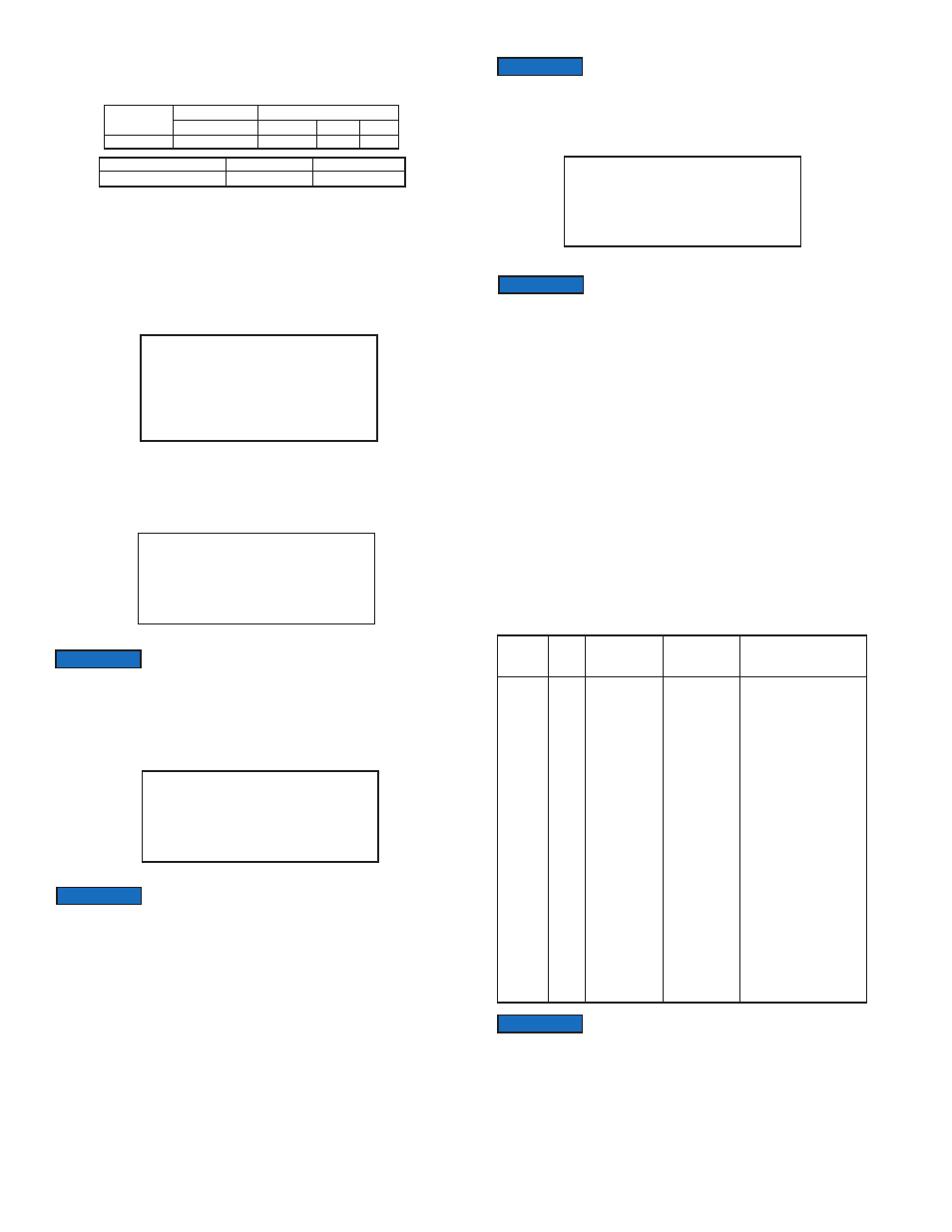
Model
GFM2-X-101
Flow Rate
(std liters/min)
up to 10
Maximum Pressure Drop
(mm H
2
0)
130
(psid)
0.18
(kPa)
1.275
Table IV - Pressure Drops
Model
GFM2-X-101 Transmitter
Weight
2.20 lb (1.00 kg)
Shipping Weight
3.70 lb (1.68 kg)
S: Ver1.4 Rev.A0
Ad: 11 Out: 0 to 5 VDC
Gas# 1 AIR
Actual content of the LCD screen may vary depending on the
model and device configuration.
NOTICE
F: 50.0 L/min
T: 75660.5 Ltr
Allow the Digital Mass Flow Meter to warm-up for a MINIMUM
of 6 minutes.
NOTICE
During the first 6 minutes of the initial powering of the GFM2
transducer, the status LED will emit a constant amber light.
NOTICE
F: 50.0 L/min
** WarmUp 2:39 **
After 6 minutes of the initial powering of the GFM2 transducer,
the status LED will emit a constant GREEN light (normal
operation, ready to measure). For GFM2 with LCD option, the screen will reflect
flow and totalizer reading. (see Figure b-4).
NOTICE
Number
1
2
3
4
5
6
7
8
9
10
11
12
13
14
15
16
17
18
19
20
21
22
23
Units of Measure
Index
0
1
2
3
4
5
6
7
8
9
10
11
12
13
14
15
16
17
18
19
20
21
22
Flow Rate
Engineering
Units
%
mL/sec
mL/min
mL/hr
L/sec
L/min
L/hr
m
3
/sec
m
3
/min
m
3
/hr
ft
3
/sec
ft
3
/min
ft
3
/hr
g/sec
g/min
g/hr
kg/sec
kg/min
kg/hr
Lb/sec
Lb/min
Lb/hr
User
Totalizer
Engineering
Units
%s
mL
mL
mL
Ltr
Ltr
Ltr
m
3
m
3
m
3
ft
3
ft
3
ft
3
g
g
g
kg
kg
kg
Lb
Lb
Lb
UD
Description
Percent of full scale
Mililiter per second
Mililiter per minute
Mililiter per hour
Liter per second
Liter per minute
Liter per hour
Cubic meter per second
Cubic meter per minute
Cubic meter per hour
Cubic feet per second
Cubic feet per minute
Cubic feet per hour
Grams per second
Grams per minute
Grams per hour
Kilograms per second
Kilograms per minute
Kilograms per hour
Pounds per second
Pounds per minute
Pounds per hour
User Defined
Once Flow Unit of Measure is changed, the Totalizer’s
Volume/Mass based Unit of Measure will be changed
automatically.
NOTICE
Page 5