Dwyer GFM2 User Manual
Page 13
9.3 Technical Assistance
Dwyer Instruments will provide technical assistance over the phone to qualified
repair personnel. Please have your Serial Number and Model Number ready
when you call.
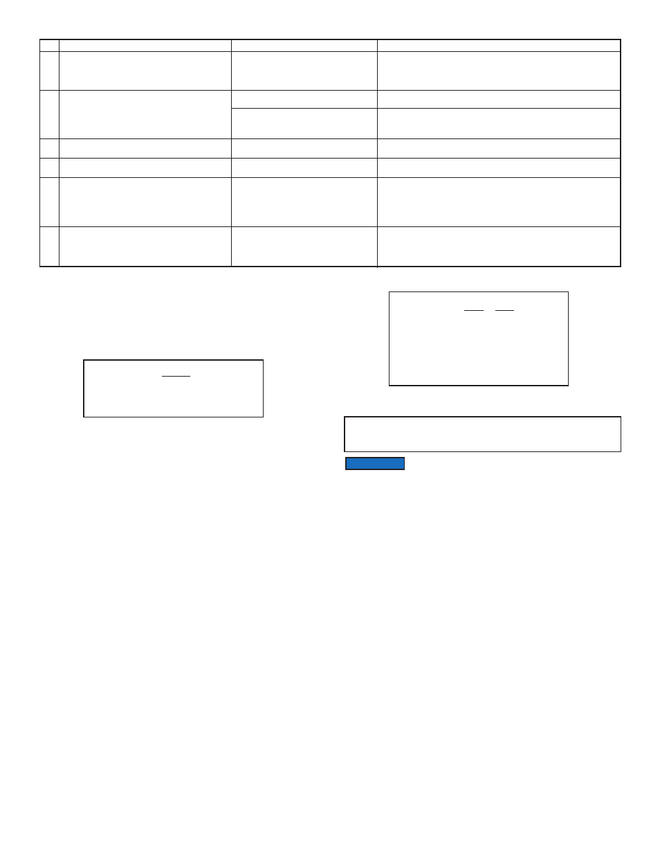
10. CALIBRATION CONVERSIONS FROM REFERENCE GASES
The calibration conversion incorporates the K factor. The K factor is derived from
gas density and coefficient of specific heat. For diatomic gases:
Note in the above relationship that d and Cp are usually chosen at the same
conditions (standard, normal or other).
If the flow range of a Mass Flow Meter remains unchanged, a relative K factor is
used to relate the calibration of the actual gas to the reference gas.
For example, if we want to know the flow rate of oxygen and wish to calibrate
with nitrogen at 1000 SCCM, the flow rate of the oxygen is:
No.
9
10
11
12
13
14
Indication
Gas does not flow through the GFM2 with inlet
pressure applied to the inlet fitting. LCD display
reading and output voltage 0 to 5 VDC signal
show zero flow.
Gas flows through the GFM2, output voltage 0 to
5 VDC signal does not respond to flow (reading
near 1mV).
The Status LED indicator is rapidly flashing with
UMBER color on /off.
The Status LED indicator is rapidly flashing with
RED color on /off.
The Status LED indicator is rapidly flashing with
RED and UMBER colors.
The Status LED indicator is constantly on with
the RED light.
Likely Reason
Filter screen obstructed at inlet.
Direction of the gas flow is reversed.
GFM2 is connected in the installation
with back pressure conditions and gas
leak exist in the system.
Sensor temperature is too low.
Sensor temperature is too high.
MCU temperature is too high (overload).
Fatal Error (EEPROM or Auto Zero
error).
Solution
Flush clean or disassemble to remove impediments or replace the
filter screen (see section 6.2). NOTE: Calibration accuracy can be
affected.
Check the direction of gas flow as indicated by the arrow on the front
of the meter and make required reconnection in the installation.
Locate and correct gas leak in the system. If GFM2 has internal leak
return it to factory for repair.
Make sure the ambient and gas temperatures are within specified
range (above 5°C).
Make sure the ambient and gas temperatures are within specified
range (below 50°C).
Disconnect power from the GFM2. Make sure the ambient
temperature is within specified range (below 50°C). Let the device
cool down for at least 15 min. Apply power to the GFM2 and check
Status LED indication. If overload condition will be indicated again the
unit has to be returned to the factory for repair.
Cycle the power on the GFM2. If Status LED still constantly on with
RED light, wait 6 min. and start Auto Zero function (see 5.3.7 Zero
Calibration). If after Zero Calibration the Fatal Error condition will be
indicated again the unit has to be returned to the factory for repair.
1
d X Cp
where d = gas density (gram/liter)
Cp = coefficient of specific heat (cal/gram)
=
Kgas
Qa
Ka
Qr
Kr
where Qa = mass flow rate of an actual gas
(sccm)
Qr = mass flow rate of a reference gas
(sccm)
Ka = K factor of an actual gas
Kr = K factor of a reference gas
=
K
=
QO = Qa = Qr x K = 1000 X 0.9926 = 992.6 sccm
where K = relative K factor to reference gas (oxygen to nitrogen)
2
If particular K factor is activated via digital interface, the user
does not need to perform any conversion. All conversion
computations will be performed internally by MCU.
NOTICE
Page 13