Dwyer AFG User Manual
Page 2
4. Avoid a sudden expansion immediately before an AFG Flow
Grid (See Fig. 2a).
5. A local contraction at the plane of the AFG Flow Grid is a use-
ful technique to increase pressure differential when velocities are
low (See Fig. 2b).
6. Where persistent swirl is expected it is advisable to install an
anti-swirl device at least 1D upstream from the AFG Flow Grid.
Note: For rectangular duct D = Width + Height of Duct/ 2
INSTALLATION
The AFG Flow Grids are supplied in kit form, and tube lengths are
cut to suit the required duct size by the customer.
The AFG Flow Grid is available in two tube diameters and lengths
(See Table 1).
Table 1: Dimensions
They may be used in square, rectangular or round ducts.
Unpack your AFG Flow Grid. The kit should contain the following
parts:
Table 2: Included Parts
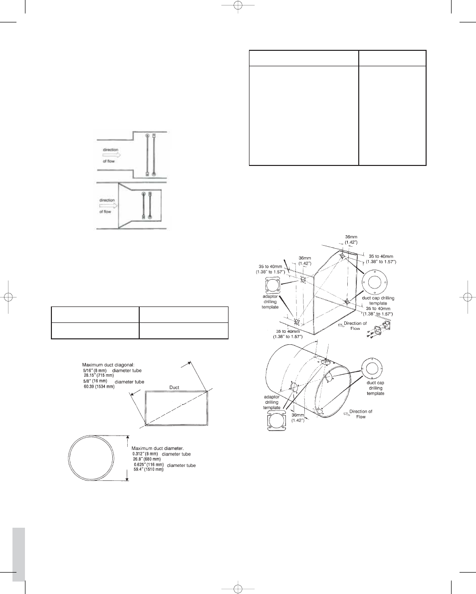
Decide on the best location for your AFG Flow Grid.
The AFG Flow Grid is designed to fit into the shortest duct sides
of a rectangular duct or across a duct diameter. Mark out the duct
to the dimensions shown in Fig. 4 and 5. Attach the self-adhesive
templates supplied, and produce the holes to the sizes indicated
on the templates. DEBURR the 1.26˝ (32 mm) diameter holes.
Introduce tubes into the duct and secure at the adapter end using
the clamping plate and No. 6 self-tapping screws supplied (See
Fig. 6 and 7). Note position of tubes relative to the direction of flow
(See Fig. 7).
page 2
Tube Diameter “A”
5/16˝ (8 mm)
5/8˝ (16 mm)
Tube & Adapters
Supplied Length Size “B”
27˝ (688 mm)
59-4/5˝ (1518 mm)
Quantity
2
2
2
2
2
2
2
2
2
2
2
2
16
Description
Adapter & Pressure Tube
Adapter Plate
Duct Cap
Cap Plate
Adapter Drilling Template
Duct Cap Drilling Template
Diaphragm
Elbow
Tube Cap
Grommet
Cap Seal
Adapter Seal
Screws, Self Tapping No. 6 x 5/8˝
Fig. 2
a) Unacceptable
b) Acceptable
Fig. 3
Fig. 4
Fig. 5
AFG iom1 1/3/06 2:00 PM Page 2