Dwyer 3200G User Manual
Page 17
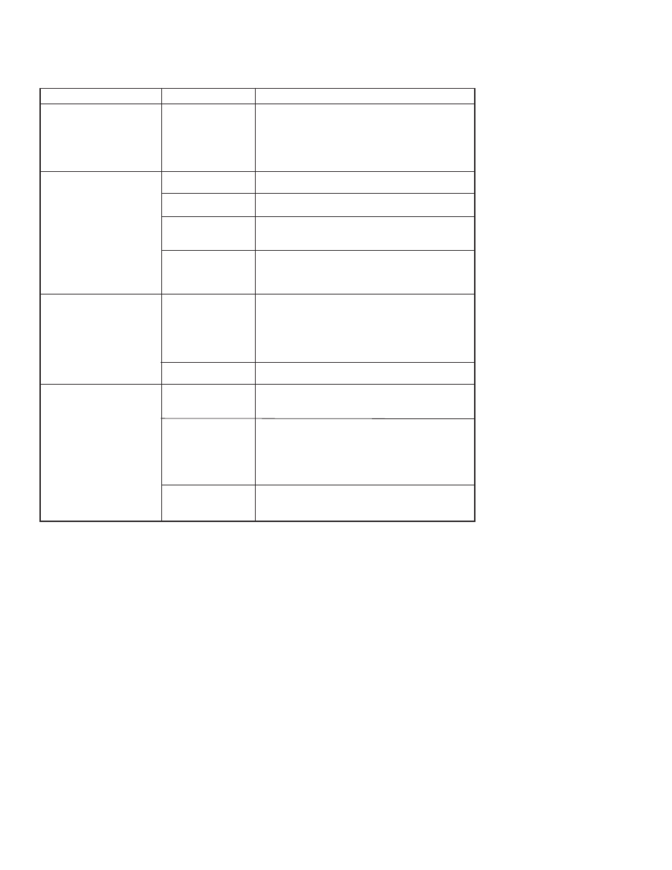
6.3 Hardware Diagnostics
If there is a failure dispite a diagnostic message on the HHT, Table
6.1 can help troubleshoot the problem.
Page 16
Symptom
Transmitter does not
Communicate with HART
®
Communicator
High Output
Erratic Output
Low Output or No Output
Potential Source
Loop Wiring
Sensor Input Failure
Loop Wiring
Power Supply
Electronics Module
Loop Wiring
Electronics Module
Sensor Element
Loop Wiring
Electronics Module
Corrective Action
• Check for a 250-550 ohms resistance
between the power supply and HHT.
• Check for adequate voltage to the transmitter
(the transmitter requires 11.9 ~ 45 Vdc).
• Check for intermittent shorts, open circuits, and
multiple grounds.
• Connect HHT and enter the transmitter test
mode to isolate a sensor failure.
• Check for dirty or defective terminals,
interconnecting pins, or receptacles.
• Check the output voltage of the power supply
at the transmitter terminals. It should be 11.9
to 45 Vdc.
• Connect HHT and enter the transmitter test
mode to isolate module failure. Check the
sensor limits to ensure the calibration
adjustments are within the sensor range.
• Check the output voltage of the power supply
at the transmitter terminals. It should be 11.9
to 45 Vdc.
• Check for intermittent shorts, open circuits, and
multiple grounds.
• Check for proper polarity at the signal terminals.
• Connect HHT and enter the transmitter test
mode to isolate an electronics mode failure.
• Connect HHT and enter the transmitter test
mode to isolate a sensor failure.
• Is the PV out of range.
• Check for adequate voltage to the transmitter
(the transmitter requires 11.9 ~ 45 Vdc).
• Check for intermittent shorts, open circuits, and
multiple grounds.
• Check polarity of signal terminal
• Check the loop impedance.
• Connect HHT and check the sensor limits to
ensure calibration adjustments are within the
sensor range.
Table 6.1 Troubleshooting