Installation, Maintenance – Blue Angel Pumps BTU30 User Manual
Page 2
movement. Failure to secure pump
could allow pump movement and
switch interference and prevent pump
from starting or stopping.
IMPORTANT: Make sure there is
adequate room for float switch to move
freely during operation.
7. Protect electrical cord from sharp
object, hot surfaces, oil and
chemicals. Avoid kinking the cord
and replace damaged cords
immediately.
8. A sump pit cover must be installed to
prevent debris from clogging or
damaging the pump.
Risk of
electrical shock! This pump
is supplied with a
grounding conductor and
grounding type
attachment plug. Use a grounded
receptacle to reduce the risk of fatal
electrical shock.
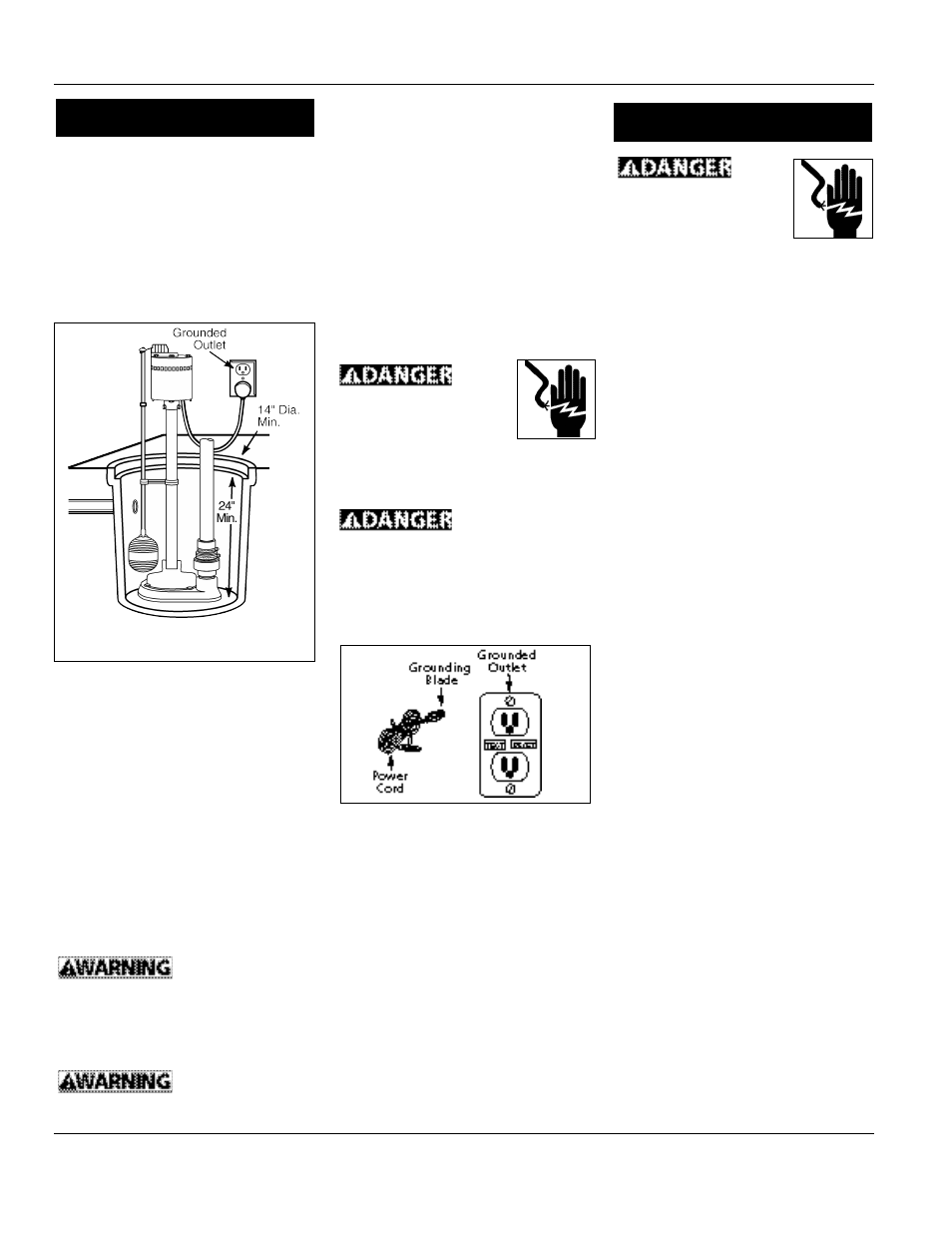
Never cut off the
round grounding
prong. Cutting the cord or plug will
void the warranty and make the pump
inoperable.
9. Insert the float switch cord plug
directly into a 120 volt outlet (See
Figure 4).
ADJUST AND TEST
1. Fill sump with water.
2. Adjust rubber grommet into a
permanent position on float rod so
that the pump switches on with
approximately 14” of water in the
sump.
3. While the pump is draining the pit,
verify that the discharge piping is
carrying the water to a point several
feet away from the foundation.
4. If the pump discharge line is
exposed to freezing temperature,
the exposed line must be pitched to
drain. Trapped water will freeze
and damage the pump.
1. A ground fault circuit interrupter
(GFCI) is required.
2. This pump is for use on 120 Volt
(single phase), 60 hz, 15 amp service
and is equipped with a 3 conductor
cord and a 3 prong grounding plug.
3. Install pump in a sump pit with
minimum size as shown (See Figure
3). Construct sump pit of tile,
concrete, steel or plastic.
4. Locate unit on a solid, level
foundation. Do not place pump
directly on clay, earth, gravel or
sandy surface. These surfaces contain
small stones, gravel, sand, etc. that
may clog or damage the pump and
cause pump failure (See Figure 3).
5. (Optional) Thread check valve (not
included) into pump body carefully
to avoid stripping or cross threading.
Do not use pipe joint sealant.
6. Connect 1-1/4” rigid pipe to rubber
boot on check valve. Reverse boot
for 1-1/2” diameter pipe. Tighten
hose clamps.
Support pump and
piping when
assembling and after installation.
Failure to do so could cause piping to
break, pump to fail, etc. which could
result in property damage and/or
personal injury.
Flood risk. If
flexible discharge
hose is used, make sure pump is
secured in sump pit to prevent
2
Operating Instructions and Parts Manual
Always
disconnect the electrical
supply before attempting
to install, service, relocate
or perform any
maintenance. If the power source is
out of sight, lock and tag in the open
(off) position to prevent unexpected
power application. Failure to do so
could result in fatal electrical shock.
Only qualified electricians should
repair this unit. Improper repair could
result in fatal electrical shock.
1. Disassembly of the motor prior to
expiration of warranty will void the
warranty. If repairs are required, see
troubleshooting chart.
2. Keep pump inlet clean and free of all
foreign objects and inspect annually.
A clogged inlet will damage pump.
3. Check pump monthly for proper
operation.
Note: Pump is equipped with an
automatic reset thermal protector.
Figure 4
Installation
Figure 3
Maintenance