Installation, Operation, Continued) – Blue Angel Pumps BSE200 User Manual
Page 3
3
www.blueangelpumps.com
Installation
(Continued)
INSTALLATION BASICS:
1. NEVER lift this product by the
electrical cords.
2. Install pump in a sump pit
that fulfills the minimum size
requirements (24 in. minimum).
Construct sump pit of tile, concrete,
steel or plastic. Do not install a pit
smaller than recommended.
3. The unit should be located and
rest on a solid, level foundation.
Do not place pump directly on clay,
earth, gravel or sandy surface. These
surfaces contain small stones, gravel,
sand, etc. that may clog or damage
the pump and cause pump failure.
Flood risk. If
fl exible discharge
hose is used, make sure pump is secured
in pit to prevent movement. Failure
to secure pump could allow pump
movement and switch interference
and prevent pump from starting or
stopping.
4. Thread the discharge pipe or pipe
nipple into the discharge flange
connection.
5. A check valve MUST be used in a
solids-handling system. Mount the
check valve in a horizontal position
or at a 45º angle with the valve pivot
on top. In a vertical position, solids
tend to lodge on the valve flapper
and can prevent it from opening.
6. Drill a 1/8 in. hole in the discharge
pipe 1 to 2 inches above the flange.
This will prevent air locking and loss
of prime at startup. A gate valve
should be installed in the system
after the check valve. This gate valve
should be a full port valve which
will pass 2 in. solids or as required by
state and local codes. The gate valve
permits removal of the pump and/
or the check valve for servicing (and
will minimize back flow mess).
7. (OPTIONAL) Install a union between
the check valve and the pump so the
pump can be removed with the least
amount of disturbance of the piping.
8. Connect 2 in. rigid pipe to check
valve.
Support
pump
and piping when
assembling and after installation.
Failure to do so could cause piping to
break, pump to fail, etc. which could
result in property damage and/or
personal injury.
9. Protect electrical cord from sharp
objects, hot surfaces, oil and
chemicals. Avoid kinking the cord and
replace damaged cords immediately.
IMPORTANT: Make sure there is
adequate room for tether switch to
swing freely during operation.
10. A pit cover must be installed to
prevent debris from clogging or
damaging the pump. All piping and
power cords will be brought through
the appropriate openings in the
basin cover. Do not modify existing
openings in any way.
All sewage basins
must be vented
to prevent a build-up of methane gas.
Consult your local codes for proper
venting. DO NOT install venting in
locations classifi ed as hazardous in
accordance with the National Electrical
Code NFPA 70.
Operation
Always
disconnect
the power source before
attempting to install, service,
relocate or maintain the
pump. Never touch pump,
pump motor, water or discharge piping
when pump is connected to electrical
power. Never handle a pump or pump
motor with wet hands or when standing
on wet or damp surface or in water.
Fatal electrical shock could occur.
1. Verify pump and switch operate
within the basin.
Risk of electrical
shock! This pump
is supplied with a grounding conductor
and grounding type attachment plug.
Use a grounded receptacle to reduce the
risk of fatal electrical shock.
Never cut off the round grounding
prong. Cutting the cord or plug will
void the warranty and make the pump
inoperable.
Operating Instructions and Parts Manual
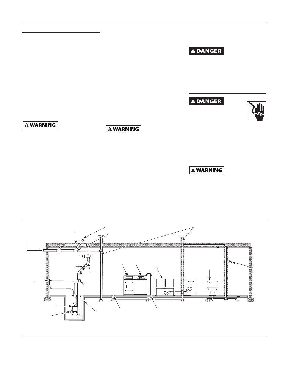
Figure 4 - Typical Installation
Three prong
grounded
outlet
equipped
with a
ground fault
interrupter
Main waste line to
sewer or septic tank
2 in. Discharge
pipe
Upper level drainage
Cleanout
Pump
Float Switch
Flange
Floor drain
Dryer
Washer
Laundry tubs
Vent pipe
Lavatory
Shower
Washer drain
45°
Elbow
2 in. Check
valve
2 in. gate valve
Union