Badger Meter Water Conditioning User Manual
Page 13
Instructions for Removing the Gear Train Assembly with Magnet
The gear train assembly can be removed and replaced without removing the turbo meter from the line
Two gear train assemblies are used with industrial turbo meters To find out what the gear train ratio is, count the number
of spindles (gear and pinions) that protrude through the five mounting holes provided in the top plate of the gear train
assembly If there are only three spindles, the gear ratio is 366:1 and if there are five spindles, the gear ratio is 1200:1
1 Remove the register, transmitter or adapter mounted on the register base
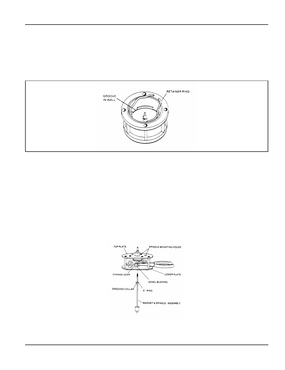
2 Release the retainer ring from the groove to free the gear train assembly from the base
Figure 6: Release the Retainer Ring
3 Use a small screwdriver to release the retainer ring from the groove in the wall adjacent to the top plate of the gear
train assembly
4 Grip the change gear spindle and lift to remove the gear train assembly with magnet from the register base
5 Remove the accessory change gear or coupling from the gear train spindle Before removing, note the location of the
change gear (or coupling) on the spindle so that it can be reinstalled in the same location
NOTE:
N
A flat surface is provided at the top of the spindle of the change gear assembly so that the setscrew in the change
gear or coupling can be properly seated and tightened to the spindle
6 Gear train assemblies are packaged with the magnet and spindle assembly disassembled from the gear train assembly
Before assembling, carefully check the spindle for minute burrs on the threaded end of the spindle If there are burrs, use
a crocus cloth and carefully remove them from the spindle This will prevent damage to the surface of the jewel bearing
when inserting the magnet spindle through the jewel-bushing in the bottom plate of the gear train assembly An "E"
ring should be mounted on the spindle If missing, remove the "E" ring from the replacement spindle and snap it into the
grooved collar near the threaded end of the spindle
Figure 7: Installing the Magnet Spindle Assembly to the Gear Train Assembly
User Manual
Page 13
November 2013