Badger Meter Water Conditioning User Manual
Page 11
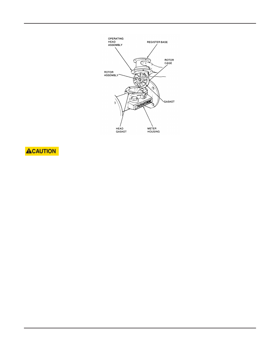
Figure 4: Turbo Meters Serviced Without Removal from the Line
EXERCISE PRECAUTION TO MAKE CERTAIN THAT FLUID DOES NOT SPRAY FROM THE METER. THE LIQUID SPRAY COULD
CONTACT ELECTRICAL EQUIPMENT AND CREATE AN ELECTRICAL HAZARD.
4 Allow the meter to drain and relieve internal pressure
5 When pressure is relieved, remove the head bolts and shift the head assembly toward the outlet-end of the meter to
release the head-to-housing seal Then lift the entire head assembly from the housing and, at the same time, tilt the
operating head up to prevent the rotor from falling off the rotor spindle
NOTE:
N
Rotors are furnished with two-pole or four-pole magnets depending on the type of accessory
6 When the operating head has been removed, lift the rotor out of the rotor cage and set it aside Remove the head gasket
NOTE:
N
A dummy cover plate is available to close the meter in the line and continue service while the operating head
assembly is being inspected or parts are being replaced
7 To remove the register base from the head assembly, loosen the seal screw on the base with a screwdriver Rotate the base
45 degrees in either direction to release it from the bayonet lock detents on the head assembly
8 The register base retaining ring is accessible through the rotor cage in the head assembly With a Truarc right-angle pliers
#1549, expand and remove the register retaining ring on the extension tube When this is accomplished, the register base
can be removed from the head assembly
9 To reinstall or replace the register base, repeat the procedure above in reverse making sure that the retaining ring has
been reinstalled on the extension tube
NOTE:
N
The head unit has a gasket bonded to the periphery of the rotor cage Depending on the chemical solution to be
metered, the gasket will be made of EPR, Buna N or Viton A material Re-inserting the head assembly into the meter
housing correctly will require compressing the gasket slightly This is done by tilting the top of the register base
on the head toward the inlet side of the meter The meter head has a pilot diameter machined into the cage at the
gasket face This pilot diameter must extend through the housing gasket inner diameter and into the housing bore
After lowering the head assembly into the housing, move the entire head assembly straight toward the inlet side of
the meter The pilot diameter must snap into the bore of the housing to provide a tight seal
10 With the head gasket aligned and the head assembly properly positioned in the housing, reinstall and tighten the head
bolts (between 90…180 in-lb of torque)
11 Close the flushing system drain valve Open the upstream valve partially, then open the downstream valve slightly which
will purge any air from the service line Then open both valves completely
User Manual
Page 11
November 2013