Iii. installation – Badger Meter CV Series User Manual
Page 4
Page 4
Form #4-20-23 11/10
III. Installation
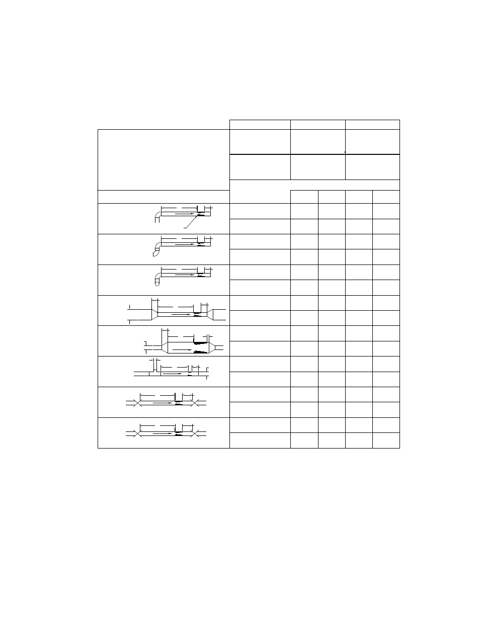
Straight Pipe Run Requirements - SSL, SSM, LPL, VISSL, VISSM, VILPL
As with most fl ow elements, proper operation and performance is dependent on the required
lengths of unrestricted upstream and downstream piping. The recommended minimum length
of the upstream side of the Venturi fl ow element depends on the type of fi tting at the start of the
straight run and the pipe confi guration. A fully developed symmetrical fl ow profi le is achieved with
the minimum upstream and downstream lengths as shown in Figure 1.
FIGURE 1
Venturi Pipe Diameter Recommendations
SSL, SSM, LPL, VISSL, VISSM and VILPL Models
NOTES:
1. For upstream and downstream lengths equal to one half the values shown, add 2 percent to the accuracy
value.
2. Any
fl ow conditioner shall be installed in the straight length between the primary element and the
upstream distance, or the fi tting closest to the element. The straight lengths between fi tting and
conditioner shall be at least 5D and the length between conditioner and Venturi meter shall be at least 8D.
3. For other fi ttings, confi gurations, consult Preso.
4. Reference - ISO-5167, "Flow Measurement Engineering Handbook", R.W. Miller.
Globe / Gate valve fully opened
Globe / Gate valve partially opened
Tee connection with different diameters
Expander
Reducer
Two elbows in different planes
Two elbows in the same plane
Single elbow
INSTALLATION DISTURBANCE
A
B
1.5 to 3D
≤ 2D
A
B
Venturi
A
B
A
B
A
B
A
A
A
A
A
A
B
B
B
B
B
B
B
A
4
4
4
5
2
2
2
2
8
8
9
10
3
3
3
3
15
15
15
4
4
4
4
20
7
6
6
6
2
2
2
2
10
8
8
8
3
3
3
3
10
8
8
8
3
3
3
3
3
6
6
6
3
3
3
3
18
14
12
12
3
3
3
3
Minimum Recommended Pipe Diameters
–1
–10
–2
–20
–3
–38
–4
–65
MODEL
THROAT SIZE
BETA RATIO
0.35
0.49
0.63
0.75
0.35
0.49
0.62
0.81
–1
–2
–3
–4
–10
–20
–38
–65
SSL / VISSL – Classical
SSM / VISSM – Nozzle
LPL / VILPL – Low-Loss
≥ 0.5D
1D to 2D
B
A
A
B
D
d or D
A
B
A
B