Installation instructions, single support – Badger Meter AR - Regular (2 to 72")" User Manual
Page 5
INSTALLATION INSTRUCTIONS, SINGLE SUPPORT
1 . Choose the proper location to install the AR Ellipse using AGA/ASME standards (or equivalent) . See
"Preso Ellipse Location
Instructions" on page 7
.
2 . Grind the surface of the pipe where the AR Ellipse is to be inserted to provide a clean area for welding .
3 . Weld the supplied thread-o-let to the pipe using standard codes for your application (1/16" weld gap recommended) . Take
care to protect the threads during the welding process .
4 . Drill a hole through the pipe wall according to
.
Model / Sensor
Weld Connector
Drill Bit
AR0 (1/2")
1/2"
5/8"
AR (7/8")
1"
1-1/8"
AR1 (1-1/4")
1-1/4"
1-3/8"
Table 2: Single support drill bit size
5 . Deburr the hole just drilled, especially on the inside of the pipe .
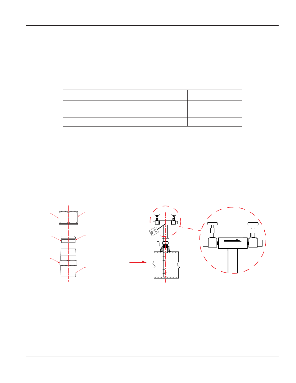
6 . Assemble the supplied compression fitting as diagrammed in
. Thread the assembled compression fitting into the
thread-o-let manually . With a wrench, tighten the body of the fitting a further 1-1/4 turns taking care not to tighten the
compression nut .
7 . Install the instrument valves (optional) at the AR Ellipse head connections . Ensure that the valves are FULLY CLOSED to
prevent them from leaking during startup .
8 . Insert the AR Ellipse through the compression fitting . Carefully push the sensor by hand further into the pipe until it
reaches the opposite wall .
9 . While holding the AR Ellipse in its fully inserted position, align the arrow located on the sensor head with the direction of
flow . See
Nut
Insert
Body
Thread nut loosely
onto body of the
compression fitting
Install insert
as shown
Threaded portion
to be installed
into weld fitting
on pipe
Field Weld
FLOW
FLOW
H
L
H
L
Nut
Insert
Body
Thread nut loosely
onto body of the
compression fitting
Install insert
as shown
Threaded portion
to be installed
into weld fitting
on pipe
Field Weld
FLOW
FLOW
H
L
H
L
Figure 5: Compression fitting
Figure 6: Sensor alignment
10 . Thoroughly tighten the compression nut in order to prevent leakage . After tightening the compression nut manually, turn
it a further 1-1/4 turns with a wrench .
User Manual
Page 5
April 2014