Badger Meter Model 3700 Data Acquisition Server User Manual
Page 3
3
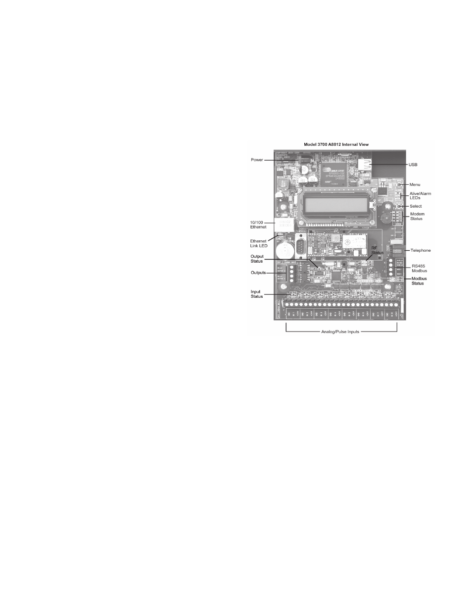
HaRdWaRE OVERVIEW
Model 3700 Features and Specifications
Processor
Arm9 embedded CPU, Arm7 io
coprocessor
Operating System
Linux
Flash Memory
16 MB flash
Memory
32 MB ram
LED
8x input, 4 modem activity, Modbus TX/
RX, power, system, IO status
Console
2 x 16 character LCD, two pushbuttons
LAN
RJ45 10/100 Ethernet, full half duplex,
auto polarity
Modem
V.34 bis, 33,600 bps (A8812-1 only)
GSM/GPRS Cellular (A8812-GSM
only)
Protocols
Modbus/RTU, Modbus/TCP, TCP/IP, PPP,
HTTP/HTML, FTP, NTP, XML
Power Supply
24VDC, 1A, class 2 wall brick
transformer.
North America: 110-120VAC, 60hz,
primary. (standard, included)
CE/Europe: 100-240VAC, 50-60hz,
primary, with interchangeable plug
adapters. (optional)
Interval Recording
User selectable 1-60 minutes. Default 15
minute interval
Serial Port1
RS-485 Modbus, supports up to 32
external devices (expandable)
Inputs
1
8 flex-IO inputs with multiple modes:
voltage, current, resistance, pulse and
status.
Voltage mode:
0-10vdc (min/max/average/
instantaneous data)
accuracy: +- 0.25% of full scale at 20°c
Current mode:
4-20mA (min/max/average/
instantaneous data)
accuracy: +- 0.25% of full scale at 20°c
Resistance mode: 100 ohms to 100k.
accuracy:
100
Ω-1kΩ +- 1% of 1kΩ at 20°c
1k
Ω - 10kΩ +- 1% of 10kΩ at 20°c
10k
Ω - 47.5kΩ +- 1% of 47.5kΩ at
20°c
47.5k
Ω - 100kΩ +- 1% of 100kΩ at
20°c
100k
Ω −10MΩ accuracy unrated.
Pulse mode:
intended for use with dry contact outputs.
(consumption/rate/runtime/status)
Standard and KYZ modes for form A and
C relay outputs
Maximum rate: 10hz
Adjustable contact closure threshold:
100
Ω to 10kΩ
Outputs
1
:
2 optically isolated outputs
type: opto-fet, dry contacts.
rating: 30VDC, 150mA max.
Isolation
2
:
The RJ45 ethernet, RJ11 Modem, pulse
outputs, and the primary side of the
power adapter are electrically isolated
from the Model 3700 main PCB board
and inputs.
Environmental
North America: Indoor, temperature
0° - 50°c, 0 - 95% humidity, non-
condensing.
CE/Europe: Indoor, temperature 5° - 40°c,
0 - 90% humidity, non-condensing.
Size
8" x 9.25" x 2.5" (203mm x 235mm x
64mm)
Mass
5lbs (2.3kg)
1
Inputs are intended for low voltage class II outputs.
2
If the product is used in a manner not specified by the
manufacture, the protection provided by the equipment may
be impaired.
electrical Connection
Hardware Installation
Step 1 - Unpack materials: Remove all materials from shipping
box and verify all required components are available
Step 2 - Mount the Model 3700 on the wall or other appropriate
location.
Step 3 - (optional) Connect any analog or pulse output sensors
you may have. For Analog sensors, 0-10V or 4-20mA sensor
types are allowed. The combined power consumption of all the
analog sensors attached to the Model 3700 must not exceed
200mA. If more current is required, use an external power
supply as shown in the wiring diagram for each input type later
in this section.
Step 4 - (optional) - Connect the Modbus network loop as
shown in the wiring diagram on the following page. Follow
the manufacturer’s instructions for installing and powering
the Modbus devices. Verify that the Modbus address settings
are unique for each device (i.e., no two devices with the same
address) and power up the device. Connect each device in the
chain by “daisy-chaining” the devices together. Observe + and
- polarity on the Modbus devices.