Installation & operation manual – Badger Meter 3050 Series Btu Monitor User Manual
Page 13
Page 13
6-11
Installation & Operation Manual
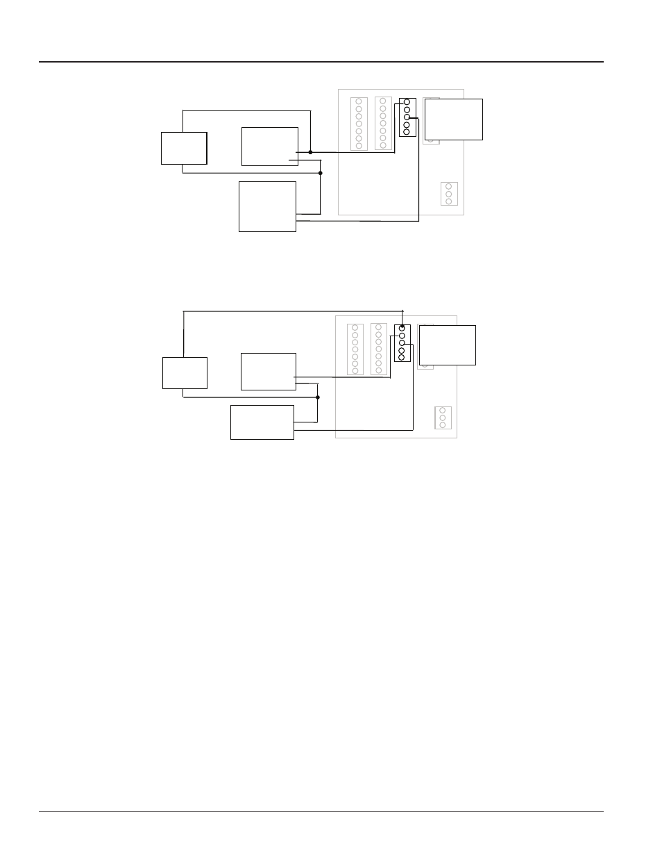
Figure 8
Relay and Switch Wiring Examples (continued)
( Chiller Control based on High Energy Usage with with indication
Figure 9
( Chiller Control based on Low Temperature Warning with indication
Chiller Motor
Starter
(1)
(2)
Power Supply
(Appropriate for
Motor Starter)
(COM)
(Line)
Indicator
Lamp
Chiller Relay
(1)
(2)
Chiller Controller
(COM)
(System Control Out)
Indicator
Lamp
1 RELAY 1 NO
2 RELAY 1 NC
3 RELAY 1 COM
4 PULSE 1 OUT
5 PULSE 2 OUT
1 RELAY 1 NO
2 RELAY 1 NC
3 RELAY 1 COM
4 PULSE 1 OUT
5 PULSE 2 OUT
Figure 10: Relay and Switch Wiring Examples (continued)
Chiller Control Based on High Energy Usage with Indication
Figure 8
Relay and Switch Wiring Examples (continued)
( Chiller Control based on High Energy Usage with with indication
Figure 9
( Chiller Control based on Low Temperature Warning with indication
Chiller Motor
Starter
(1)
(2)
Power Supply
(Appropriate for
Motor Starter)
(COM)
(Line)
Indicator
Lamp
Chiller Relay
(1)
(2)
Chiller Controller
(COM)
(System Control Out)
Indicator
Lamp
1 RELAY 1 NO
2 RELAY 1 NC
3 RELAY 1 COM
4 PULSE 1 OUT
5 PULSE 2 OUT
1 RELAY 1 NO
2 RELAY 1 NC
3 RELAY 1 COM
4 PULSE 1 OUT
5 PULSE 2 OUT
Figure 11: Relay and Switch Wiring Examples (continued)
Chiller Control Based on Low Temperature Warning with Indication