Electrical installation – Badger Meter 3100 Series Flow Monitor User Manual
Page 9
Page 9
2-12
Installation & Operation Manual
Electrical Installation
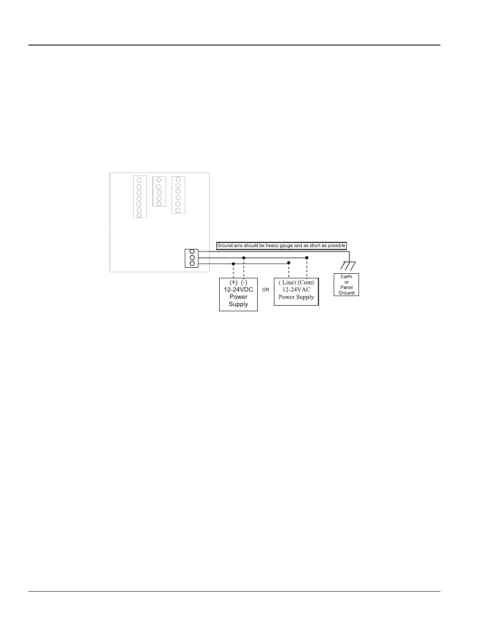
Power Supply Wiring
The Series 3000 Flow Monitor requires 12-24 VDC/VAC to operate. Check the Specifications on page 23 for DC current draw
and AC Volt-Amp requirements.
A fused circuit is always recommended. Connect the positive of the power supply to the Series 3000 terminal marked
(ACL/DC+), and connect the negative of the power supply to the Series 3000 terminal marked (ACC/DC-).
If a Badger Meter Data Industrial plug-in power supply (Model A1026, A-503) is being used, connect the black-white wire to
the terminal marked (ACL/DC+) and the black wire to the terminal marked (ACC/DC-).
Earth
3
LV AC/DC(-) 2
LV AC/DC(+) 1
POWER
Figure 3: Power Supply Wiring
Flow Sensor Wiring
The Series 3000 flow sensor inputs are extremely versatile, designed to accept either two-wire or three-wire pulse inputs
(Data Industrial 200 Series, 4000 Series) or Analog inputs. Although different rear panel terminals are used, all parameters are
set with the LCD/keypad interface. There are no internal or external jumpers, switches or potentiometers to move or adjust.
The following pulse input types are accommodated.
•
Pulse-DI: Used for all Badger Meter Data Industrial Flow Sensors. Provides an internal pull-up resistor and uses “K”
and “Offset” values for calibration.
•
Pulse–K Factor: Accepts non zero-crossing inputs but provides no internal pull-up, classical “K” ( pulses/gallon)
values for calibration.
•
Pull-up-K Factor: Provides an internal pull-up resistor and uses classical “K” ( pulses/gallon) values for calibration.
NOTE: All the above pulse input types wire the same as shown in Figure 4. See the Programming Flow Chart on
page 16 for required input configuration.