External pullup resistor, External pullup resistor 8, Tion (see – Badger Meter K-Factor Scaler User Manual
Page 8: Figure 3
1
2
3
4
5
6
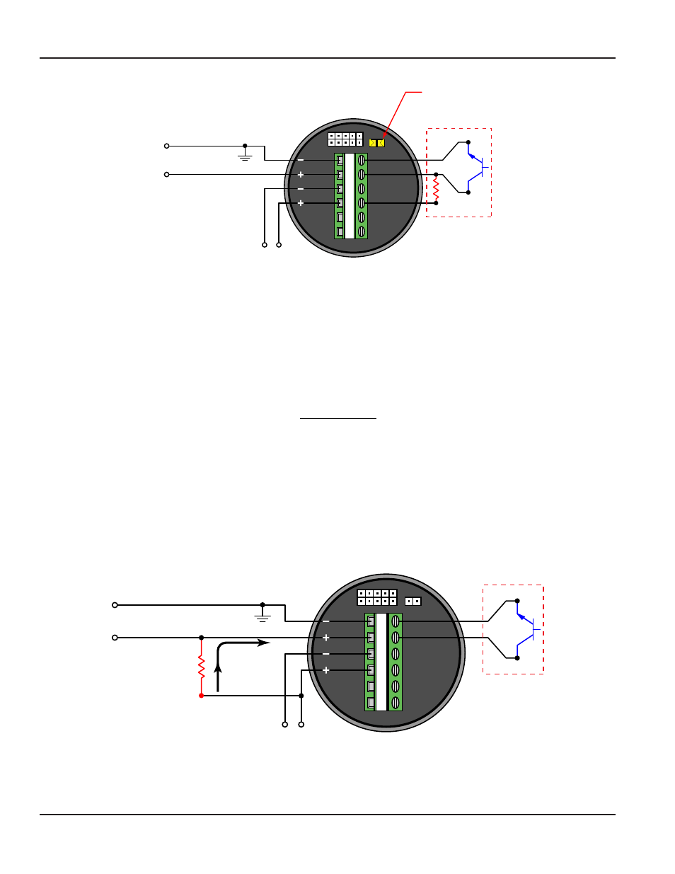
Internal 3.6k Ω
Pullup
Resistor Jumper
3.6k Ω
TB1
Open Collector
Pulse Output
Internal
8 mA
Maximum
Output
Output
Vin
Vin
Vin
Figure 3: Wiring schematic with internal pullup resistor in circuit
External Pullup Resistor
Using an external pullup resistor offers the end user greater flexibility in controlling the output pulse provided by the
K Factor Scaler Power sources and receiving devices differ in individual situations This fact requires the use of different pullup
resistor values Connection of the external pullup resistor is between the receiving device’s input and external power source
(see
) The power source voltage is the maximum input voltage (of the pulse) to the receiving device Refer to the
following equation to help determine the pullup resistor value needed
R =
Supply Voltage
Current
Where:
R = Resistor value in ohms
Supply Voltage = External supply voltage connected to the external pullup resistor
Current = Input current required by the receiving device in amps
After the resistor value is calculated, make sure in the following equation that power (P) is less than or equal to 0 25 Watts P
represents the output power capability This value should not exceed 0 25 Watts Damage to the K Factor Scaler circuit is likely
by exceeding this value Raising the resistor value will decrease the available power output and safeguard the circuit
1
2
3
4
5
6
TB1
Open Collector
Pulse Output
250…10k
Pullup
Resistor
+V
Internal
100 mA
Maximum
Output
Output
Vin
Vin
Vin
Figure 4: Wiring schematic using an external pullup resistor
Signal Conditioner, B220-885 K Factor Scaler and B220-900 Programming Software Kit
Page 8
November 2013