Introduction, Operating principle, Introduction 5 – Badger Meter K-Factor Scaler User Manual
Page 5: Operating principle 5
INTRODUCTION
The Blancett K Factor Scaler is a field adjustable frequency divider, which converts the output signal from a turbine meter
or like device with a magnetic pickup or pulse output to an input compatible with a PLC, RTU, CPU data acquisition card or
similar totalizer device The adjustable frequency divisor, referred to as a K factor, allows pulses sent from a turbine meter to
accumulate into a unit recognizable by an end device, such as a PLC, for counting and display
The use of different K factor values allows the device to display in any number of volumetric measurements such as gallons,
cubic meters, liters, barrels, and like units The calibration sheet usually provided with a turbine meter lists a nominal K factor
tested to a specific volumetric flow rate The K factor when placed into the K Factor Scaler provides an output pulse for
each unit of volume that passes through the turbine Any units of volume are possible by recalculating the K factor with the
appropriate conversion factor
In addition, if the K factor is set to one, the K Factor Scaler becomes a preamplifier converting the frequency from a low output
level turbine meter to the logic level needed by a PLC or CPU data acquisition card
The programmable K Factor Scaler provides a lower cost alternative to the Blancett model B220-880 K Factor Scaler The
programmable version uses fewer components, reducing the size of the board and enclosure
OPERATING PRINCIPLE
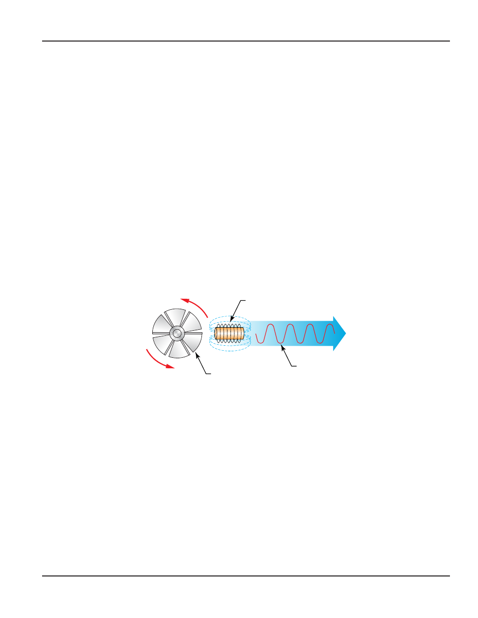
Fluid passing through the turbine causes it to rotor to spin at a speed proportional to the fluid velocity As each rotor blade
passes through the magnetic field, the blade generates an AC voltage pulse in the pickup coil at the base of the magnetic
pickup (see
) These pulses produce an output frequency proportional to the volumetric flow through the meter The
output frequency with further processing represents flow rate and/or totalization of fluid passing through the flow meter
Turbine Rotor
Magnetic Pickup
or
Other Frequency
Output Device
Output
Signal
Figure 1: Schematic illustration of electric signal generated by rotor movement
The K Factor Scaler input amplifier modifies the signal generated by the turbine The amplifier sends the modified signal to an
onboard microcontroller, which counts pulses up to a predetermined number controlled by the K factor value The range of
the K factor is between 1…999,999,999 The predetermined value once reached triggers a pulse from the output circuitry
The K factor is user adjustable through the programming interface The duration of the output pulse is also selectable At the
end of the output pulse, the internal counters reset to zero and the process starts over
User Manual
Page 5
November 2013