Installation, Electrical connections, Power – Badger Meter K-Factor Scaler User Manual
Page 7: Turbine meter, Pulse output, Internal pullup resistor, Installation 7
INSTALLATION
Refer to
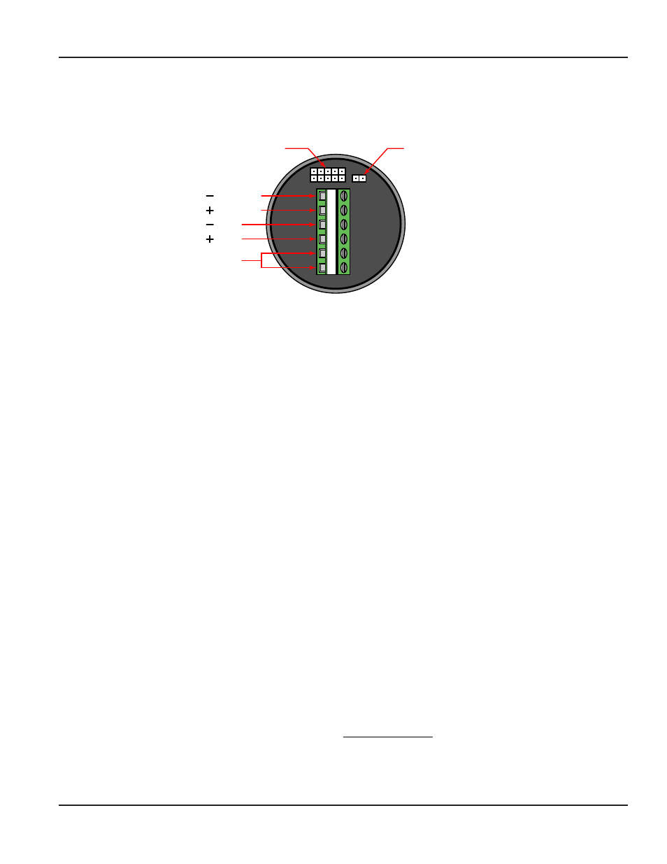
for the I/O terminal connections The board connections include power input, turbine meter input, and the
pulse output to a totalizing device
1
2
3
4
5
6
Signal
Input
Output
Output
Vin
Vin
Programming
Port
Internal 3.6k Ω
Pullup
Resistor Jumper
Figure 2: Input/Output terminal connections
Enclosure Mounting (necessary for CSA certification)
If supplied without an enclosure you must mount the circuit board assembly within a certified Killark one inch NPT model Y-3
conduit elbow outlet box to maintain the CSA “Ordinary Locations” certification
Electrical Connections
The board connections include power input, turbine meter input, and the pulse output to a totalizing device
Power
The K Factor Scaler requires 8 5…30V DC to operate and is diode protected
shows the supply polarity
Turbine Meter
The turbine meter connections are non-polarized Blancett recommends shielded, twisted pair wire for this connection
Pulse Output
Either the internal or an external pullup resistor is required for the K Factor Scaler to provide an output pulse An onboard
jumper controls the pullup resistor selection With the jumper installed, the internal pullup resistor is connected Without the
jumper, an external pullup is required Refer to
for the I/O terminal connections
Internal Pullup Resistor
The internal pullup resistor allows for a simple installation, but be careful to ensure that the device being connected to
the pulse output can accept voltage levels as high as the supply feeding theK Factor Scaler Another important setup
consideration when using the internal pullup resistor is to make certain the output pulse from the K Factor Scaler can supply
enough current for the receiving device to read the pulse Calculation of the available current that the K Factor Scaler can
supply to the receiving device uses the following equation (see
Available Current =
(Input Voltage - 0.7V)
(3600Ω + 47Ω)
Using the above equation the maximum current available at an input voltage of 30V is 8 mA Verify that the receiving device
input current requirement is below this value for proper operation Otherwise, an external pullup resistor less than 3 6 kΩ
is required
User Manual
Page 7
November 2013