Commissioning data, Operating limits, Control device adjustment – Airedale Air Cooled Condensers R410A User Manual
Page 18: Standard ac type fans, Control device, Adjustment
CR12
– CR105
Condensers
18
Condensers
Installation & Maintenance : 6680953 V1.2.0 02/2013
Commissioning Data
OPERATING LIMITS
Standard Variable Speed Head Pressure Control
Minimum Ambient Air DB °C
-20°C
Maximum Ambient Air DB °C
+48
Optional On/Off Head Pressure Control
Minimum Ambient Air DB °C
-0°C
Maximum Ambient Air DB °C
+48
(1)
For conditions outside those quoted, please contact Airedale.
(2)
Low ambient kits are available for applications with ambient temperatures below those quoted,
please contact Airedale.
CONTROL DEVICE ADJUSTMENT
STANDARD AC TYPE
FANS
When the condenser is matched to an Airedale indoor unit, head pressure control is
provided by the indoor unit.
Unmatched condensers are supplied with a head pressure control device which can be
either:
1
Variable speed control (standard)
2
On/Off pressure switch (optional)
The control device is factory pre-set.
To check the setting connect a pressure gauge with scale reading up to at least 45bar to
the pressure tapping located in the outlet manifold of the condenser and watch the
operation of the fan as the pressure changes. If the settings require adjustment, follow the
instructions set out below and check new settings as explained above.
CAUTION
Before carrying out any work, ensure that the isolator is switched off.
Variable Speed Control
The fan speed is controlled via alteration of the supply voltage which corresponds to a
particular condensing pressure. The output voltage from the controller varies between a
maximum of 95% and a minimum of 40% of the mains voltage (ie 220 Volts down to
approximately 90 Volts on a 230 Volt supply) as the condensing pressure varies within a
band of 5 Bar.
The control system is suitable for temperatures down to -20°C.
The pressure set point corresponding to the maximum output voltage can be adjusted by
means of a potentiometer internal to the case of the controller.
Sizes CR12 - CR30
Factory setting: Set
= 26 barg - Standard Thermostatic Expansion Valve
= 22 barg - Optional Electronic Expansion Valve
Sizes CR50 - CR105
Factory setting: Set
= 26 barg (58%) - Standard Thermostatic Expansion Valve
= 22 barg (49%) - Optional Electronic Expansion Valve
Differential = 5 barg (11%)
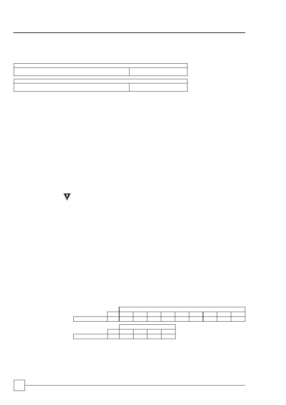
To adjust the set points, find the required setting below and adjust the relevant
potentiometer:
SET POINT Potentiometer position (%)
%
20
30
40
50
60
70
80
90
100
Range 0 - 45 barg barg
9
13.5
18
22.5
27
31.5
36
40.5
45
DIFF Pot position (%)
%
5
10
15
20
Range 0 - 45 barg barg
2.3
4.5
6.8
9.0
Minimum Speed = 40%
Maximum Speed = 100%