Installation data – Airedale Air Cooled Condensers R410A User Manual
Page 13
Condensers
CR12
– CR105
Condensers
13
Installation & Maintenance : 6680953 V1.2.0 02/2013
Installation Data
PIPEWORK INSTALLATION - GOOD PRACTICES
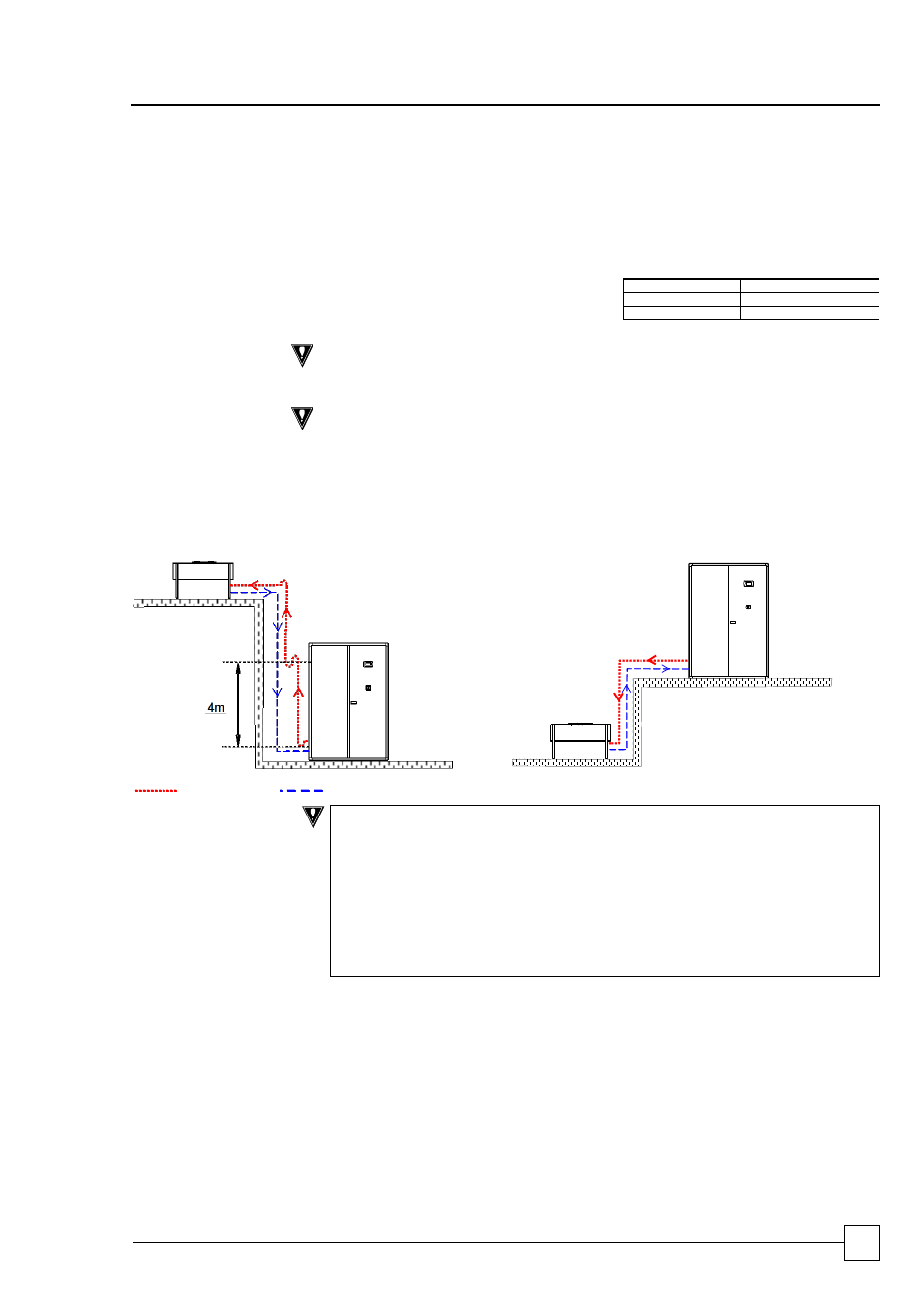
Oil Traps
For long vertical rises in discharge lines, it is essential that oil traps are located every 4m
to ensure proper oil movement / entrapment. In addition there should be an oil trap at the
exit of the air handling unit before a vertical riser is applied (refer to example below).
Pipe Supports
The following table identifies the maximum
distance between pipe supports on vertical
and horizontal pipe runs.
Pipe O/D (inches)
Support distance (m)
3/8 - 7/8
1.0
1 1/8 - 2 1/8
2.0
CAUTION
All pipework should be clamped prior to insulation being applied.
Pipe lengths
CAUTION
DISCHARGE LINE:
Maximum pressure loss for discharge pipework 42 kPa.
Minimum velocity for discharge risers 5 m/s, to ensure good oil return.
LIQUID LINE:
Maximum pressure loss for liquid line pipework 21 kPa.
Minimum velocity for liquid line 1.5 m/s, to ensure good oil return.
Condenser above Air Handling Unit
Condenser below Air Handling Unit
t
Discharge Line
Liquid
IMPORTANT
It is the responsibility of the installing contractor/site engineer to check the pipe
size/refrigerant charge is correct for each system installation and application.
Split systems may require additional oil which should be added to the low
pressure side of each compressor.
Design should be in accordance with accepted refrigeration practice to ensure
good oil return to the compressor(s) under all normal operating conditions.
REMEMBER excessive pressure loss in interconnecting pipework will impair
system performance; this should be factored in during the design of the system
and where necessary oil traps employed.