Fnc.2 (fnc.3), Src.2 (src.3), O.typ – West Control Solutions TB 45 Temperature Monitor User Manual
Page 36: O.act, Lim.2, Lim.3, Fai.1, Fai.2, Sb.er, Inf.1
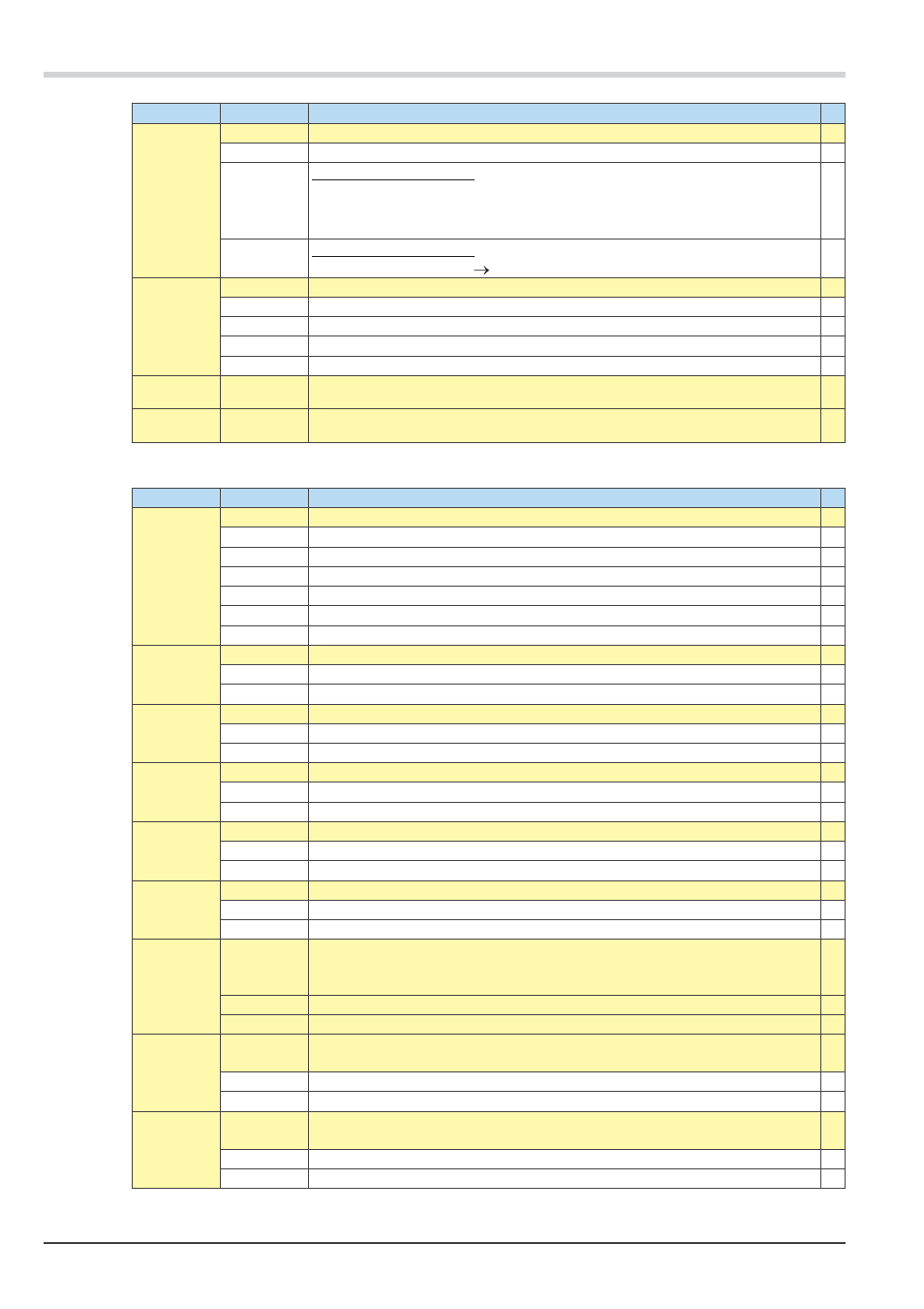
Name
Value range Description
Fnc.2
(Fnc.3)
Function of pre-alarm 2 / 3
0
switched off
1
Measured value monitoring
If a limit is exeeded an alarmsignal is executed. It becomes resetted automatically,
when the measured value has returned to the "acceptable" range (including hystere-
sis).
2
Measured value monitoring + alarm status latch. A stored limit value can be reset via
error list or a digital input (
LOGI/ Err.r).
Src.2
(Src.3)
Source for pre-alarms 2 /3
0
Process value = absolute alarm
1
Process value - limit value LC = relative alarm
3
Measured value of the analog input INP1
4
Measured value of the analog input INP2
µ
C.Std
OFF; 1 …
9999999
Monitoring operating hour (only visible with BlueControl!)
C.Sch
OFF; 1 …
9999999
Monitoring duty cycle (only visible with BlueControl!)
Output Out.2, Out.3
µ
Name
Value range Description
O.tYP
Type of OUT (only Out.3 - analog)
µ
0
Relay/logic
1
0...20 mA continuous
2
4 ... 20 mA continuous
3
0...10 V continuous
4
2...10 V continuous
5
Transmitter supply
O.Act
Direction of operation
0
Direct / normally open
1
Inverse / normally close
Lim.2
Signal limit 2
0
Not active
1
Active
Lim.3
Signal limit 3
0
Not active
1
Active
FAi.1
Signal INP1 fail
0
Not active
1
Active
FAi.2
Signal INP1 fail
µ
0
Not active
1
Active
Sb.Er
System bus error message: internal system bus communication error. The output is
set in case of an error in the internal system bus communication, no communication
with this instrument occurs
0
Not active
1
Active
Inf.1
Message Inf.1 status. The Inf.1 signal is generated, when the limit value for the ope-
rating hours is reached.
0
not active
1
active
Inf.2
Message Inf.2 status. The Inf.2 signal is generated, when the limit value for the num-
ber of switching cycles is reached.
0
not active
1
active
Configuration level
36
Configuration
TB 45