Operation, Input & output ports – SHIMPO FGS-50PXL User Manual
Page 3
Drive Assembly Control
Speed controls A & B can easily be adjusted and assigned to control
the test and return travel rates of the force gauge. The position of
the LED (A or B) determines which control is active.
The upper and lower travel limits can be adjusted by loosening
the thumb limit screws and sliding them to the desired position.
NOTE: Don’t forget to hand tighten the limit screws when the
desired position is reached.
Operating Procedures
The FGS-50PXH and FGS-50PXL feature two types of operation:
• Mode Operation
• Program Operation
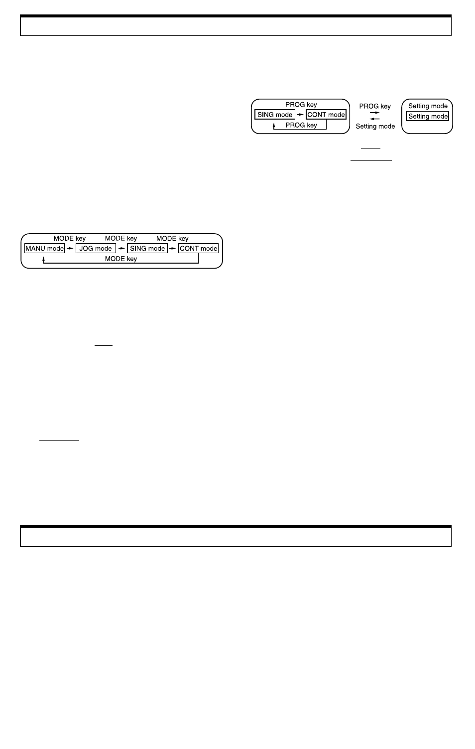
Mode Operation
By pressing the “mode” button the LED will change between
four basic types of operation:
Operation
The test stand is programmed as follows:
1. Press "home". This will be the starting position of the
program.
2. After selecting one of the two programs, press the “set”
button. The LED number in the far upper left corner of
the display will show a flashing “0” followed by a flashing
"-----".
3. Using the “push” and “pull” buttons, move the stand into
position.
4. Select speed “A” or “B” using the “speed” button.
5. Select the amount of stop time (in seconds) by pressing
the “tim” button. The LED will scroll through 1,2,3,4,5,P
(“P” stands for pause; the program will pause at this
position until either “push” or “pull” are pressed to resume
the rest of the program).
6. Press the “set” button again to store this first point. The
LED number in the upper left corner of the display will
change to the next digit.
7. To set the next point simply repeat steps 2-5. The LED in
the upper left corner of the display can display numbers 0-9,
up to ten potential set points.
8. When all points have been programmed, press the “set”
button again to store the program.
9. Press either the "push" or "pull" button to begin the program.
10. To cancel a set point, press the “rst” button while in the
“set” mode; press “rst” once more to move the next
programmed point into position.
11. If “stop” is pressed while the program is at one of its stop
positions, the entire program is canceled.
12. To erase the whole program you must scroll through each
set point and erase them individually.
Input & Output Ports
Three communication/data ports are located on the right side of
the test stand. Use these ports along with the appropriate cable(s)
(optional) to download information from a compatible force gauge
and upload information to a compatible data acquisition device.
PORT 1: FGC.V.X Input Port
DFS Series (Requires DFS-CTRLCABLE) - Receives
overload information from a DFS series gauge. If an overload
condition exists, the drive assembly will stop, thus preventing
permanent load cell damage. As an added feature, the test stand
will stop at force setpoints when the "hi" and "lo" limits are
programmed on the DFS.
FGV Series (Requires FGV-CTRLCABLE) - When interfacing
to a FGV series force gauge, the test stand will receive overload
and measuring data. If an overload condition exists, the drive
assembly will stop, thus preventing permanent load cell damage.
NOTE: The force gauge must be turned on (display showing)
for the overload protection feature to work.
1. MANU - Stand moves in either the “push” or “pull” direction
(depending on the button depressed) and will continue to move
in direction selected until “stop” is pushed or until one of the
two manual switches are tripped.
2. JOG - Moves in either the “push” or “pull” direction as long as
the corresponding button is being depressed.
3. SING - Performs single cycles between the upper and lower
manual switches. The length of pause time (1-5 seconds) can
be selected by depressing the “tim” button. The speed for the
“pull” direction will always be setting “A” and the “push”
direction setting “B” (the stand switches automatically). The
stand can run either compression or tension cycles, depending
on which direction the stand is initially directed. The total
number of cycles run can be obtained by depressing the “length/
speed” button until there is no LED showing.
4. CONT - Same as the SING mode, except that the stand will
continuously cycle between the upper and lower manual
switches.
Program Operation
Before initiating the program mode it is best to adjust the speed
settings until each are at satisfactory levels.
The program will begin from the "home" position. The factory
setting for the home position is the upper manual limit switch.
1. SING - The stand will run a single program.
2. CONT - The stand will continuously cycle through the
program.
NOTE: When dip switch #2 is in the down position the upper
manual limit switch is the home location. When in the up
position, the lower manual limit switch is the home position.
By pressing the “prog” button the LED will move between the
two types of program operation:
PORT 2: FGC.V Output Port
(Requires FGV-RS232 cable) - Transmits RS232C data to an
external device when a FGV series force gauge is mounted to
the stand (this port is not needed for the DFS series).
PORT 3: Length Output Port
(Requires FGV-ANALOG cable) - Transmits an analog output
voltage proportional to the length meter display. The relationship
between output and display is 10mV/mm. Since the length meter
data is generated by the test stand, this port can be used with any
force gauge mounted to the stand.
NOTE: If the LED display shows rate (mm/min), the voltage
output will still reflect length meter data.