Wiring check: wiring check range, 1 . checking procedure – KYORITSU 6305 Quick Manual User Manual
Page 28
−
27 −
KEW6305
KEW6305
Wiring check:
WIRING CHECK
Range
10. Wiring check:
WIRING CHECK
Range
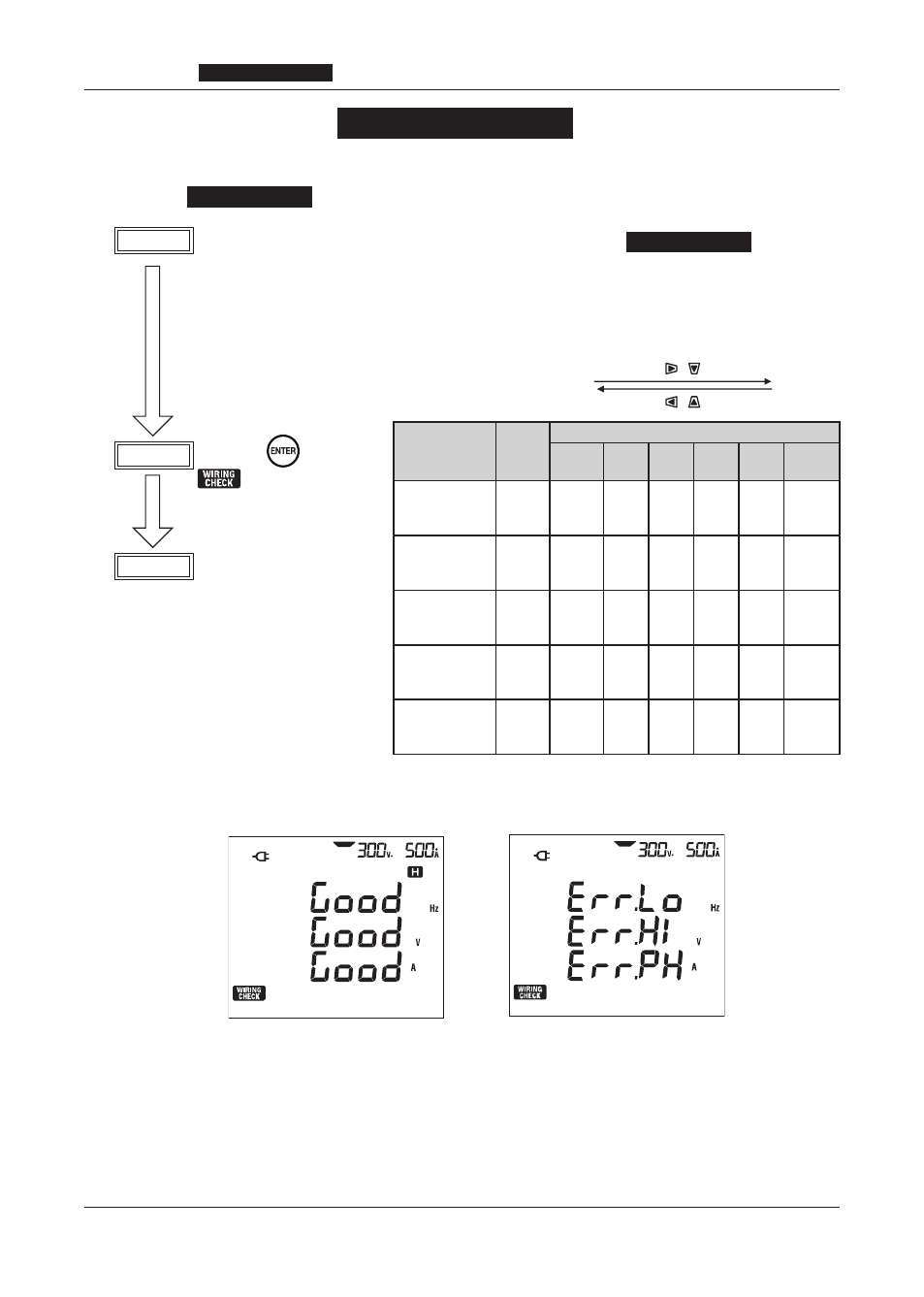
10-1.Checking procedure
Select the
WIRING CHECK
Range for checking proper connection.
STEP1 After connections are complete, set the Function switch to the
WIRING CHECK
Range.
Then present voltage, current, power factor and electric power (instantaneous value) are
displayed on the LCD as shown in the table below.
STEP2 Press the
Key.
symbol keeps
blinking for about 5 sec.
STEP3 Check result will be
displayed as follows.
Everything is OK.
Error is found.
* Check results may be affected if great power factors (0.5 or less) exist at the measurement sites.
Wiring system
(Setting no. 01)
Display
position
Items to be displayed
Screen
1
Screen
2
Screen
3
Screen
4
Screen
5
Screen
6
3P4W
3P3W3A
Top
Middle
Bottom
f
V(avg)
A(avg)
V1
V2
V3
A1
A2
A3
P1
P2
P3
PF1
PF2
PF3
DEG(V1)
DEG(V2)
DEG(V3)
3P3W
1P3W
Top
Middle
Bottom
f
V(avg)
A(avg)
V1
V2
−
A1
A2
−
P1
P2
−
PF1
PF2
−
DEG(V1)
DEG(V2)
−
1P2W (3ch)
Top
Middle
Bottom
f
V
A(avg)
V
−
−
A1
A2
A3
P1
P2
P3
PF1
PF2
PF3
−
1P2W (2ch)
Top
Middle
Bottom
f
V
A(avg)
V
−
−
A1
A2
−
P1
P2
−
PF1
PF2
−
−
1P2W (1ch)
Top
Middle
Bottom
f
V
A1
V
−
−
A1
−
−
P1
−
−
PF1
−
−
−