KYORITSU 3127 User Manual
Page 21
- 18 -
(7) Set the Range switch to “OFF” position, and remove test leads from the
instrument.
Note)
●
The voltage warning mark stays on during a measurement and it blinks when
voltages of AC/DC 30V or higher exist on the circuit under test.
●
When measuring low resistances (if currents larger than the rated current are
output) over a long period of time, KEW3127 consumes large power and will
overheat. When this happens, further tests are automatically inhibited and the
over-temperature symbol appears on the display. The instrument must then
be left cool down. Testing shall be resumed when symbol disappears.
Short-circuit currents at a start of measurement may get lower when the“ ”
symbol appears.
●
Depending on the ambient temperature or measured resistances,
the“ ”symbol may appear and interrupt a PI measurement.
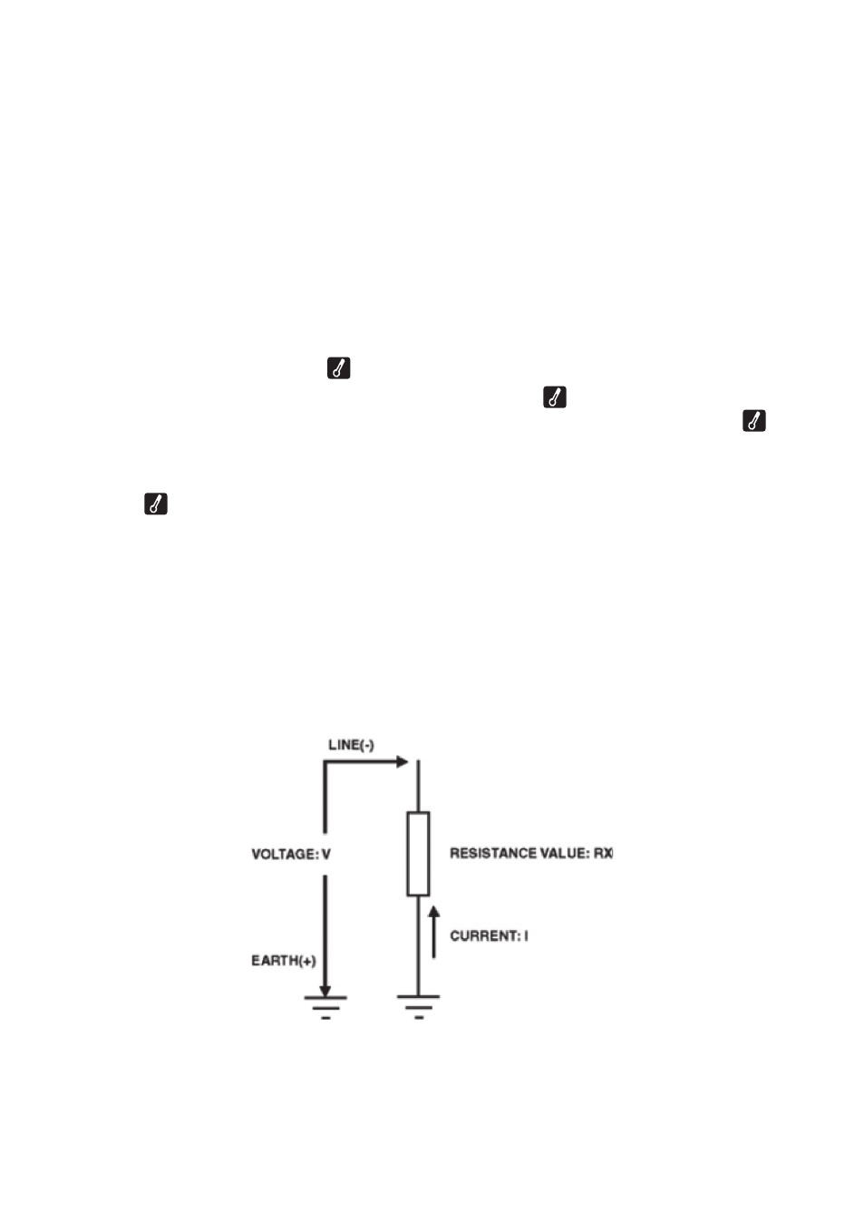
Principle of Insulation Resistance Measurement
Resistance value can be obtained by applying a certain high voltage to the
resistance (insulation resistance) and measuring the flowing current.
Resistance value = Voltage / Current
(RX = V / I)